
led display circuit diagram

The schematic also includes various LED-related circuits, such as LED flashers powered by AC line, astable multivibrators, digital timers, and sequencers. Notably, this version of a simple 10 LED chaser does not use a 555 timer due to its high cost at local electronics stores. Instead, an oscillator is created using two sections of a 4011 NAND gate, which is inexpensive and widely available. The circuit employs a 4017 CMOS counter and a 4011 CMOS NAND gate. Incandescent lamps can be used in place of LEDs by connecting transistors to drive them. The base of each transistor connects to the outputs of the 4017 through a 1K resistor, with one end of the lamp connected to the positive supply and the other to the transistor's collector, while the emitter is grounded. Depending on the lamps used, power transistors with heat sinks may be required. This simple counter can count pulses and serves as the basis for various applications, such as customer counters commonly seen at store entrances. The circuit accepts any TTL-compatible logic signal and can be easily expanded with additional components like the 7490, 74HC90, 7447, and 74HC47. More digits can be added by constructing additional circuits and connecting them to the existing ones.
This design does not rely on a microprocessor; instead, it utilizes an EPROM and multiple counters. The LEDs are matrixed and strobed rapidly to illuminate all 70 LEDs, with horizontal strobes employed, contrasting with the vertical strobes used in most large signs. This approach was chosen for its electrical efficiency.This page features a replacement circuit for the LM3909 LED Flasher / Oscillator using discrete components. The circuit is functionally the same as the integrated LM3909 but has a minor variations in values of the components used.
The LM3909 can still found but is fairly expensive, one possible source is Futurlec. The LM3909 is also available through some surplus electronics sources but usually only in quantities of hundreds or thousands of pieces. Naturally the circuit will not be as compact as the integrated circuit but it does offer the ability to adjust individual component values and can be less expensive than the integrated circuit itself. Let`s blink some leds again. Well, fading could be more accurate term. Meaning of this article is to show you an easy circuit that lets you light up your case with slowly alternating colors or just to make your power led come alive.
Color changing FireWheel could be also cool, what do you think This is by no means a step by step how to but I think that it will be enough anyway. In LM324 there are 4 operation amplifiers. We used only two of them so you have an option to build another similar circuit around the IC. This way you can use second potentiometer to control the another circuit and it`s fading speed etc. LEDs shimmer randomly as though on fire LED power supplies for AA cells 1. 5 Volt LED Flashers AC Line Powered LEDs Astable Multivibrator 9 Second Digital Readout Timer 9 Second LED Relay Timer 16 Stage Bi-Directional LED Sequencer, other sequencer and flaser circuits 10 Stage LED Sequencer 28 LED Clock Timer Fading Red Eyes Two Transistor LED Flasher 16 Stage Bi-Directional LED Sequencer Expandable 16 Stage LED Sequencer LED Photo Sensor Circuit I don`t know why, but people like blinking lights.
You see LED chasers everywhere, in TV shows (Knight Rider), movies, and store windows. This schematic is my version of a simple 10 LED chaser. There is no 555 timer used because at my local electronics store they are over $4 Cdn. Instead, an oscillator made up of two sections of a 4011 NAND gate is employed. This chip is very inexpensive and extremely common. 4017 CMOS Counter, 4011 CMOS NAND Gate. You can also use incandescent lamps instead of LEDs. Use transistors to drive them by connecting the base of the transistors to each of the outputs of the 4017 through a 1K resistor. Connect one end of the lamp to the positive supply. Then connect the other end to the collector of the transistor. The emitter then goes to ground. Depending on the lamps, you may need power transistors that are heat sinked. This simple counter can be used to count pulses, as the basis for a customer counter (like you see at the doors of some stores), or for anything else that may be counted.
The circuit accepts any TTL compatible logic signal, and can be expanded easily 7490, 74HC90, 7447, 74HC47, Common Anode 7 Segment LED Display, You can add more digits by building a second (or third, or fourth, etc. ) circuit and connecting the pin 11-6 junction of the 74LS90 and 74LS47 to pin 14 of the 74LS90 in the other circuit.
You can keep expanding this way to as many digits as you want. This sign I designed uses no microprocessor. It has an eprom and multiple counters. As in most electric signs, the LEDs are matrixed, and strobed very quickly to make it possible for all 70 LEDs to appear lit. This sign is strobed horizontally, unlike most large signs which are strobed vertically. I did it this way because electrically it was sim 🔗 External reference
Related Circuits
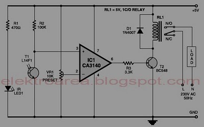
Typically, home appliances are controlled using switches, sensors, and similar devices. However, physical interaction with switches can pose safety risks in the event of a short circuit. The circuit outlined here eliminates the need for physical contact to operate...
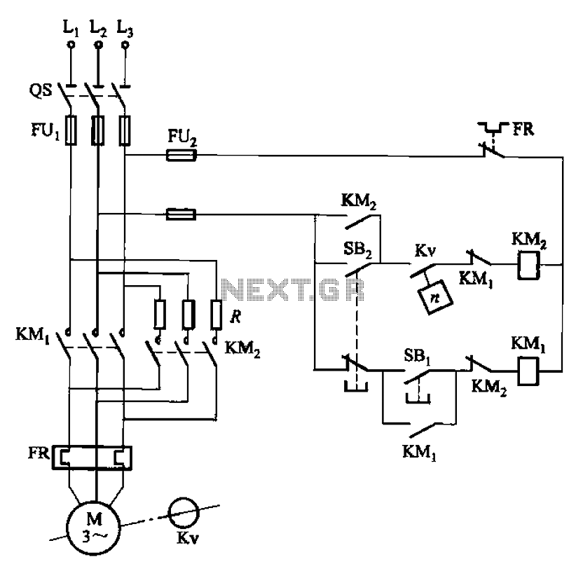
The circuit depicted in Figure 3-124 operates without an intermediate relay. Kv serves as the speed relay, activating when the electric motor speed exceeds 120 r/min while the contact is closed. If the speed drops below 100 r/min, the...
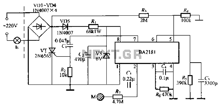
The BA2181 is a dimming controller that utilizes ASIC technology for touch-based stepping dimming of lights. It operates with low power consumption and has strong anti-interference capabilities. The device is compact and stable, making it suitable for various applications....
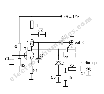
A very simple DIY crystal oscillator circuit that uses a quartz crystal for frequency stability and a suitable RF transistor. It employs a second or third harmonic crystal for operation. This DIY crystal oscillator circuit is designed to generate stable...
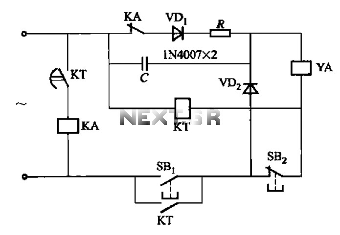
AC solenoid DC circuit operation operates similarly to a DC contactor circuit, but the AC solenoid pull circuit is illustrated in the provided figure. The capacitance C is generally between 1-10 microfarads (µF), with a minimum of 20 microfarads...
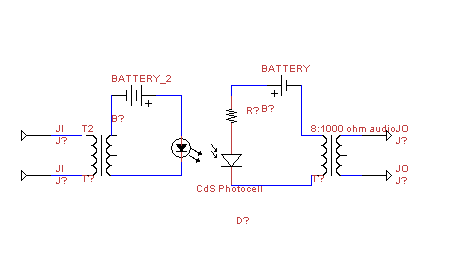
This circuit transmits audio information using light waves. It employs amplitude modulation (AM) to vary the intensity of an LED, which is detected by a cadmium sulfide photocell that changes its resistance based on light intensity. The circuit includes...