
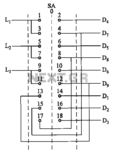
Switching two-speed motor control circuit
The motor switch control circuit is designed to facilitate the operation of a motor at two distinct speeds while enabling counter-steering functionality. This is particularly useful in applications where bidirectional control is required, such as in robotics or automated vehicles.
The circuit typically consists of a motor, a switch mechanism, and control logic to manage the speed settings. Two separate speed settings can be achieved through the use of a multi-position switch or a relay system. The switch connects the motor to different voltage levels or current paths, resulting in varying speeds.
For instance, in one configuration, activating the switch in one position may connect the motor to a higher voltage, allowing it to operate at full speed. Conversely, switching to another position may reduce the voltage, thereby decreasing the motor speed.
Counter-steering is achieved by reversing the polarity of the motor's supply voltage. This can be done using an H-bridge configuration, which enables the motor to rotate in either direction. The control logic may include microcontroller signals or simple transistor switching to manage the direction and speed of the motor effectively.
Safety features, such as current limiting resistors or thermal protection, can be integrated into the circuit to prevent damage from overcurrent situations. Additionally, feedback mechanisms, such as encoders or potentiometers, can be employed to provide real-time information on the motor's speed and position, enhancing the overall control strategy.
Overall, this motor switch control circuit is an essential component in systems requiring precise motor control with the capability to operate at multiple speeds and in both forward and reverse directions.Motor switch control circuit shown in Figure offers two speeds counter-steering i.e. two speeds in the opposite direction.
Related Circuits
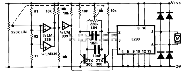
A limitation of the bi-directional proportional motor control circuit is that when the potentiometer is in its center position, the motor does not stop but continues to creep. This occurs due to the challenge of precisely adjusting the potentiometer...
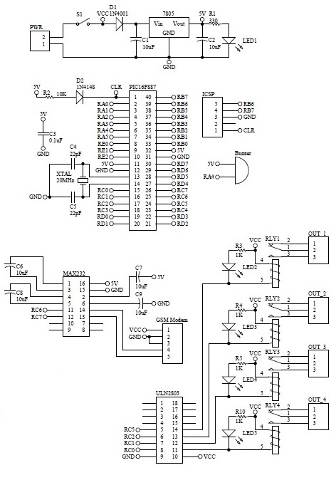
How to turn on equipment by sending SMS `1111` to switch it ON and switch off the equipment by sending SMS `0000`. The GSM switch will receive instructions for either load 1 (L1), load 2 (L2), load 3 (L3),...
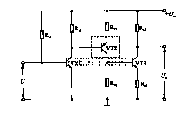
A multi-stage DC-coupled amplifier circuit utilizes NPN type transistors. Each stage is designed to achieve an appropriate operating point at the base, resulting in a stepwise increase in collector potential, which subsequently reduces the final output voltage range. To...
VOX is a voice-activated switch commonly used with microphones as an alternative to traditional push-button switches. The VOX can be connected to various audio equipment featuring an external speaker for coupling. The activation threshold is adjusted using the volume...
This circuit is designed to serve as a programmable LED display for various applications. It features an 8 x 32 LED dot matrix interfaced with a Xino (or Arduino). In addition to the display, the circuit includes two buttons...
These two tank circuits appear to broaden the operating spectrum. The accompanying information sheet indicates that when both circuit stages oscillate at the same frequency, the power output reaches its maximum. This suggests that if the tunable tank circuit...