
One of a thyristor AC switch circuit

The thyristor AC switch circuit is an essential component in various applications requiring efficient control of AC power. The circuit operates by utilizing a thyristor, a semiconductor device that can control power flow and switch on or off based on gate trigger signals. This non-contact switching capability allows for minimal wear and tear, contributing to the longevity and reliability of the system.
In the half-wave AC power supply configuration shown in Figure 16-43 (a), the thyristor is connected in series with the load. During the positive half-cycle of the AC input, the thyristor can be triggered to conduct, allowing current to flow through the load. The conduction continues until the current drops below a certain threshold, at which point the thyristor turns off, effectively blocking the negative half-cycle of the AC waveform. This results in a pulsed output voltage across the load, which can be controlled by adjusting the firing angle of the thyristor.
Conversely, in the full-wave AC power supply configuration depicted in Figure 16-43 (b), two thyristors are employed to control both halves of the AC waveform. This arrangement allows for the conduction of current during both the positive and negative cycles, providing a more efficient power delivery to the load. The full-wave configuration enhances the average output voltage and reduces ripple, making it suitable for applications requiring smoother power delivery.
Overall, thyristor AC switch circuits are integral in various industrial and consumer applications, such as motor control, lighting dimmers, and heating systems, due to their effectiveness in managing AC power with minimal losses and high reliability.Do not trigger circuit thyristor AC switch circuit, due to its simple, economical, non-contact, so widely used. Circuit shown in Figure 16-43. It is a single-phase thyristor sw itching circuits. Figure 16-43 (a) for the half-wave AC power supply, Figure 16-43 (b) full-wave AC power supply.
Related Circuits
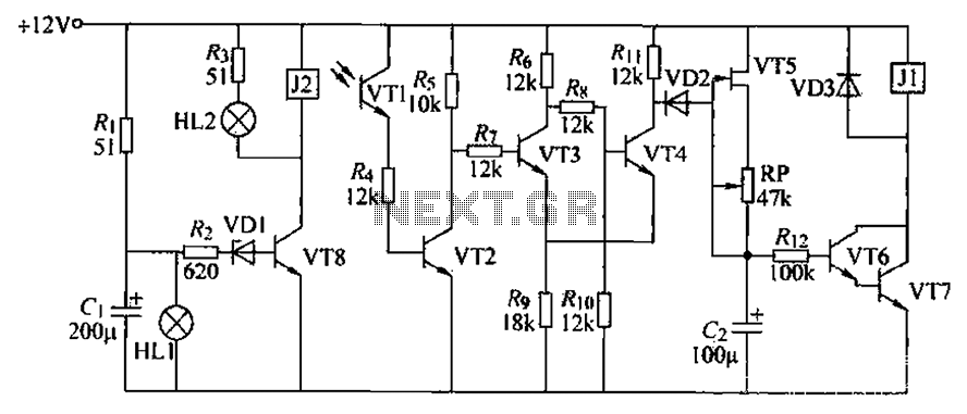
A blocking material monitoring circuit is presented. When the optical path is obstructed by the material, the phototransistor VT1 turns off, which subsequently turns off transistors VT2, VT3, and VT4. This arrangement is coupled to a flip-flop configuration. When...
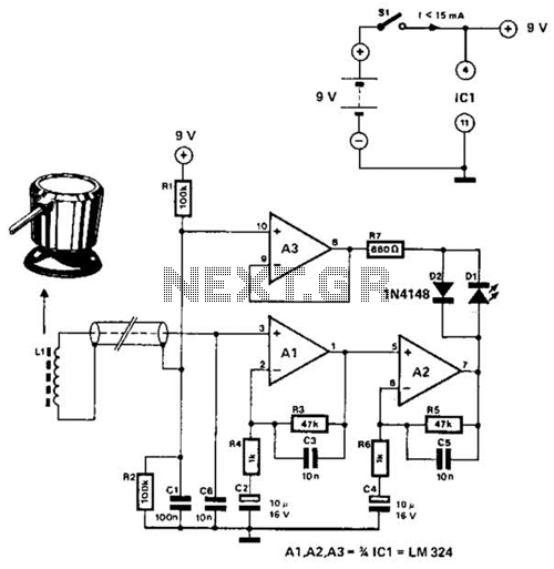
The circuit utilizes the principle that in an RL circuit, the pulse width across the inductor is proportional to the inductance. This circuit indirectly measures the inductance using a digital voltmeter (DVM). The measurement range is approximately 5 to...
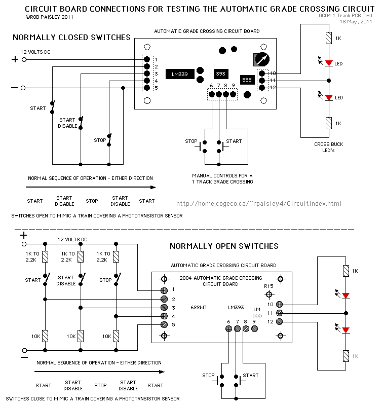
The protected section of track can be of any desired length and does not need to be equal on both sides of the crossing. The circuit operates bidirectionally and can be linked with other grade crossing circuits to provide...
Although it may lack the aesthetic appeal of traditional mercury barometers, which feature long glass tubes mounted on intricately carved and polished wood, the Torricelli barometer being discussed serves as a functional equivalent and electronic replica of the classic...
Magnetic stripe reader, electric circuit theory, logic operation. The wiring diagram does not connect the transistor in the circuit. The collector pin of the transistor connects to the tip pin of the jack. The base pin of the transistor...

The Electro Harmonix Big Muff Pi circuit would likely benefit from the incorporation of a modern input-jack power connection and a DPDT bypass switch. The specific types of transistors and diodes used in the circuit are not specified. It...