
Acid-Rain Monitor Circuit
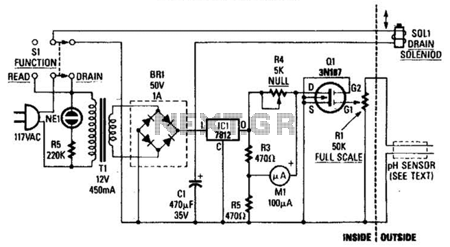
The circuit involves a field-effect transistor (FET), specifically Q1, whose drain-to-source resistance (R_DS) is affected by the pH level of the sample solution. When the acidity of the sample changes, it alters the gate voltage of Q1, which in turn modifies the resistance. This change in resistance directly affects the current (I) flowing through the bridge circuit, where the bridge is typically configured to measure small changes in voltage that correspond to variations in current.
The bridge circuit may consist of resistors arranged in a Wheatstone bridge configuration, allowing for precise measurements of the current changes. The output voltage from the bridge is then related to the pH level, enabling the circuit to function as a pH sensor.
For optimal performance, it is essential to consider the characteristics of Q1, including its threshold voltage, transconductance, and output conductance, as these parameters will determine the sensitivity and accuracy of the pH measurement. Additionally, the selection of appropriate reference electrodes and calibration techniques will enhance the reliability of the readings obtained from the circuit. The overall design should ensure minimal noise and interference, which can affect the precision of the pH measurement. The drain-to-source resistance of Ql varies depending on the acidity of the sample presented to Ql`s gate circuit. That variable resistance varies the current flowing through the bridge; that current is proportional to pH. 🔗 External reference
Related Circuits
Christmas is approaching, and it is the time of year when electronics students and hobbyists consider creating a Christmas circuit for their homes, particularly one that features flashing lights. Numerous circuits and kits are available that can flash various...
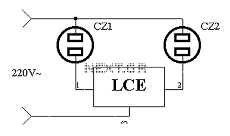
The application circuit operates the device as illustrated below. It is designed for cooling electrical equipment, typically utilizing a cooling fan to dissipate heat. The LCE employs a synchronous control socket on the device and its connections remain unchanged....
A JFET-bipolar cascode circuit is designed to deliver complete video output for driving the cathode of a CRT. The configuration offers an approximate gain of 90. The cascode arrangement mitigates issues related to the Miller capacitance of the JFET...
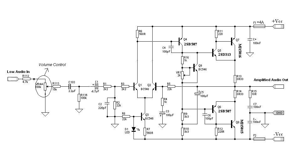
Designing an audio amplifier from scratch using discrete components is an engaging task, as it enables users to create amplifiers that meet diverse requirements. Audio amplifiers can enhance low-level sounds from mobile devices, making them louder and more vibrant....
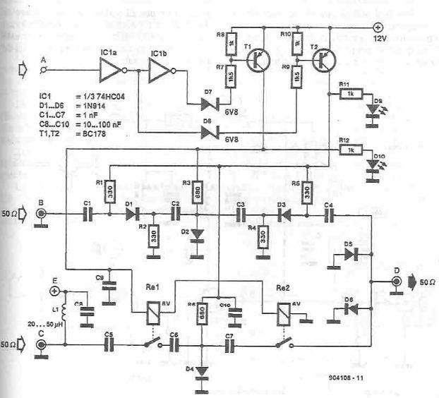
This antenna selector circuit diagram electronic project is constructed using standard electronic components and facilitates the switching between two FM antennas through a logic signal. The gates IC1b and IC1a manage the switching and interface between the required logic...
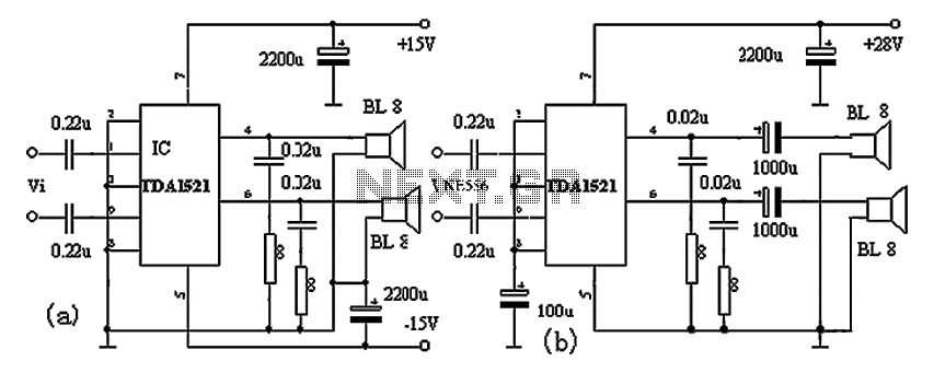
The TDA1521A amplifier circuit is designed for high-fidelity applications with minimal external components. It is suitable for powering Walkman devices or transforming low-powered computer speakers. The TDA1521A comes in a nine-pin single in-line plastic package and offers output power...