
am-fm-sw active antenna
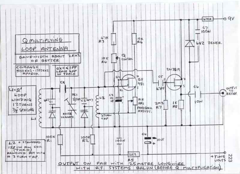
This active antenna circuit enhances the reception capabilities of various radio frequency bands by amplifying weak signals. The design allows for flexibility in tuning and performance optimization based on the frequency of interest. The choice of inductors (L1) is crucial; the 470 µH coil is optimal for AM frequencies, while the 20 µH coil is more effective for shortwave frequencies, allowing the user to adapt the circuit for specific applications.
Powering the circuit with a 9-volt battery ensures portability, making it suitable for mobile applications. When utilizing an external power supply, the inclusion of a 0.04 µF capacitor serves as a filter to reduce high-frequency noise that could interfere with signal clarity. The standard 18-inch telescoping antenna provides a compact yet effective means of signal capture, and the output jack J1 facilitates easy connection to a variety of receivers, ensuring compatibility with both consumer and professional-grade equipment.
Overall, this active antenna circuit is an efficient solution for enhancing radio reception across multiple frequency bands, particularly in environments where traditional wire antennas may be impractical or ineffective.This circuit shows an active antenna that can be used for AM, FM, and shortwave (SW). On the shortwave band this active antenna is comparable to a 20 to 30 foot wire antenna. This circuit is designed to be used on receivers that use untuned wire antennas, such as inexpensive units and car radios. L1 can be selected for the application. A 470uH coi l works on lower frequencies ( AM ). For shortwave, try a 20uH coil. The unit can be powered by a 9 volt battery. If a power supply is used, bypass the power supply with a. 04uF capacitor to prevent noise pickup. The antenna used on this circuit is a standard 18" telescoping type. Output is taken from jack J1 and run to the input on the receiver. 🔗 External reference
Related Circuits
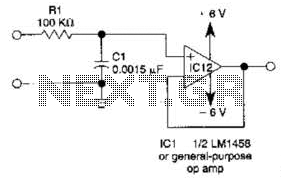
This simple filter utilizes an RC section as the filter element, incorporating a voltage follower to manage other frequencies. The -3 dB point is calculated as 1/(6.28 * RXCV), resulting in a response that drops 6 dB per octave...
Here's something that has always bugged me: light waves are about 5000 Angstroms in wavelength, while atoms are more like 1 Angstrom across. Atoms are thousands of times smaller than light waves, yet atoms obviously interact very strongly with...
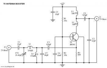
This is a straightforward circuit for a UHF band TV antenna booster that provides a gain of 15 dB. This low-cost antenna booster is simple and easy to construct. The UHF band TV antenna booster circuit is designed to enhance...
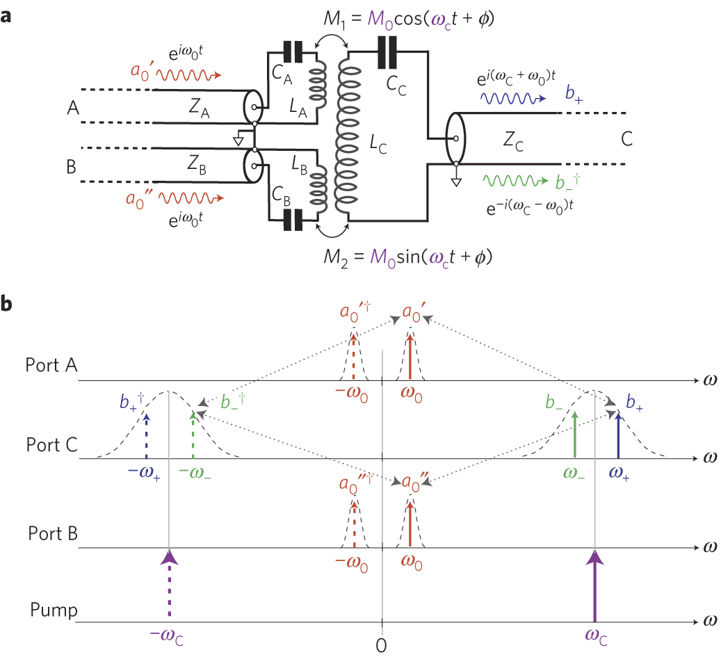
The circuit schematic of the UDC consists solely of dispersive components. Two low-frequency series LC resonators, with equal inductances (LA=LB) and capacitances (CA=CB), are connected to two input semi-infinite transmission lines, designated as A and B. These resonators are...
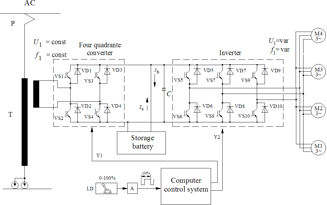
The diagrams illustrate the startup sequence of the TEP-60 diesel engine starter in relation to current accumulators: 1 - battery current without a supercapacitor block (SCB) when the traction generator operates in starter mode; 2 - battery current with...
This circuit is designed to be used in conjunction with the standard 4 foot square loop used in MW for long distance reception. The circuit described is intended for use with a 4-foot square loop antenna, which is a common...