
Active Antenna
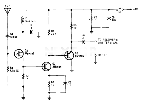
The circuit described involves a multi-stage amplifier configuration designed to effectively handle signals received from antennas that are significantly shorter than 1/4 wavelength. Such antennas inherently exhibit very small and frequency-dependent impedances, which complicates the matching process across a wide frequency range. To address this challenge, the circuit employs a field-effect transistor (FET) configured as a source follower (Q1). This configuration is advantageous because it presents a high input impedance, allowing it to effectively interface with the antenna's characteristics without loading it down.
Following the FET source follower, transistor Q2 is implemented as an emitter follower. This stage serves dual purposes: it provides a high-impedance load to Q1, ensuring that the signal integrity is maintained, and it also presents a low-drive impedance to the subsequent common-emitter amplifier stage represented by Q3. The common-emitter configuration of Q3 is critical, as it is responsible for delivering the necessary voltage gain for the overall amplifier circuit.
Transistor Q4 plays an essential role as well, acting to transform the output from Q3. This transformation can involve level shifting or impedance matching, depending on the specific design requirements of the circuit. The arrangement of these transistors allows the amplifier to effectively manage the signal from the antenna while maintaining high performance across a range of frequencies, thus ensuring optimal operation of the entire system.Antennas that are much shorter than 1/4 wavelength present a very small and highly relative impedance that is dependent on the received frequency. It is difficult to match impedances over a decade of frequency coverage. Instead, input stage Q1 is an FET source-follower. A high-impedance input successfully bridges antenna characteristics at any frequency. Transistor Q2 is used as an emitter-follower to provide a high-impedance load for Q1, but more importantly, it provides a low-drive impedance for common-emitter amplifier Q3, which provides all of the amplifier's voltage gain. Transistor Q4 transforms Q3' 🔗 External reference
Related Circuits
The signal booster, constructed using several transistors and supporting components, provides an RF gain ranging from approximately 12 to 18 dB across a frequency range of about 100 kHz to over 30 MHz. The RF signal is directly coupled...
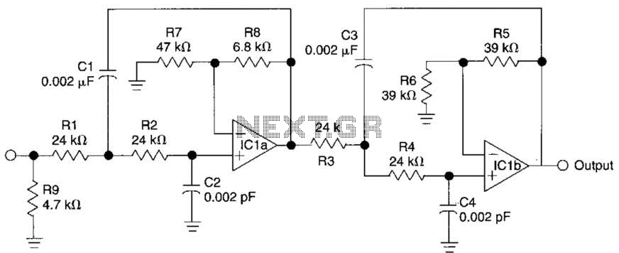
This circuit is a fourth-order low-pass filter designed for operation at kilohertz frequencies. The component values for resistors R1, R2, and capacitors C1, C2, as well as resistors R3, R4 and capacitors C3, C4 can be adjusted for functionality...
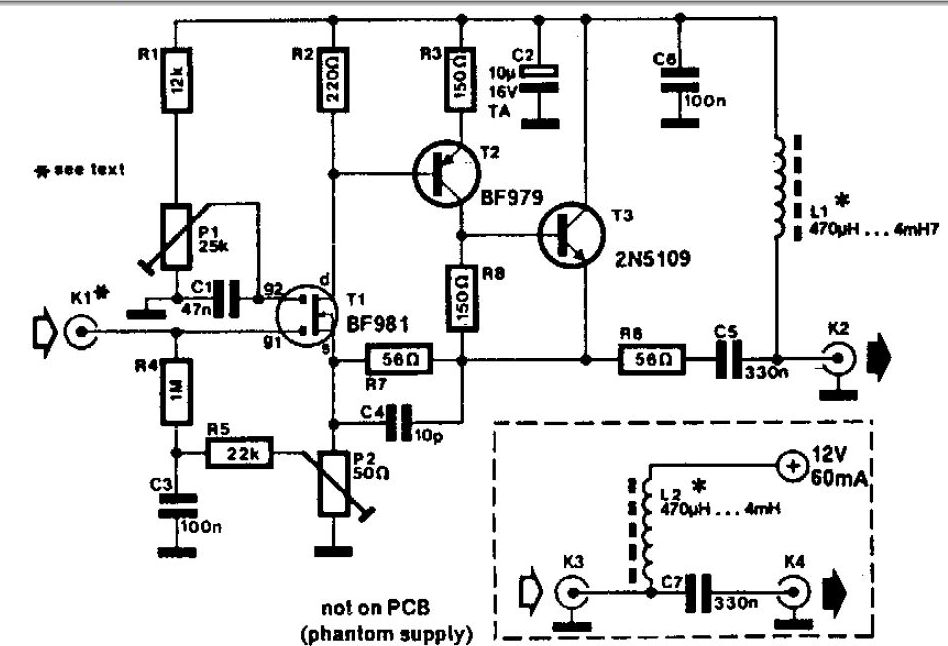
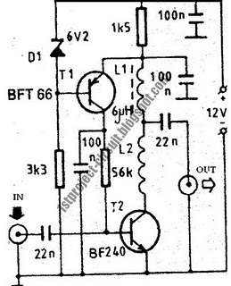
A whip antenna measuring between 30 to 50 cm is capable of receiving signals from 10 MHz to over 220 MHz. The circuit incorporates a BF981 dual-gate MOSFET (T1), which offers low noise characteristics, high input impedance, and enhanced performance. The...
This design presents a simple antenna amplifier electronic circuit project, which can be utilized based on the provided circuit diagram. The antenna amplifier operates effectively within a frequency range of 1 to 300 MHz. It is suitable for high...
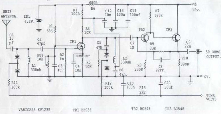
This circuit is designed to amplify the input from a telescopic whip antenna. The preamplifier is intended to operate within the medium waveband, covering frequencies from approximately 550 kHz to 1650 kHz. The required tuning voltage ranges from 1...
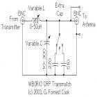
This circuit is for a QRP (low power) antenna tuner, a.k.a. a transmatch, for use in the short wave amateur radio bands from 3-30 MHz. It allows a wide variety of antennas to be connected to a low power...