
RS-232 Laser Transciever circuit
The laser source for this project is an inexpensive laser pointer pen. As well as being readily available, the circuit is designed in such a way so that the laser pointer is not damaged, and can be used for other experiments. Because this is an entry level circuit, costs have been kept to a minimum around $20 for the transceiver and approximately $10 for the transmitter (excluding the laser pointer).
Why use a laser? A laser as a communications medium has some unique properties compared to other forms of media. A line-of-sight laser beam is useful where wires cannot be physically connected to a remote location. A laser beam, unlike wires, also does not require special shielding over longer distances. Lasers offer at least an order of magnitude longer distances compared to infrared LEDs. Although RF transmitters may offer longer distances than line-of-sight lasers, they are subject to interference from other transmitters. Since the laser medium is line-of-sight and the beam being only several millimeters in diameter it is very difficult for the data stream to be tapped. This offers secure communication since any attempts to intercept the laser beam would be detected at the receiver as a loss in data. A laser medium also allows for the sender and receiver to be galvanically isolated from each other.
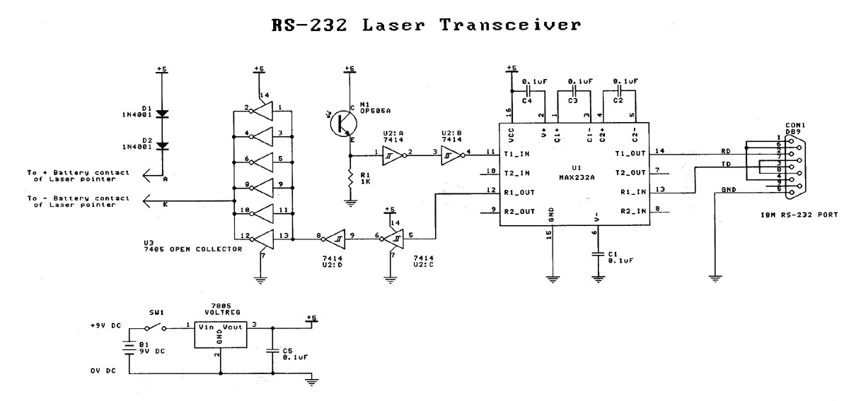
The transceiver is based on the MAX232A IC for generating and receiving RS-232 compatible voltage signals. The receiving sensor is an NPN infrared photo-transistor (OP505A). An infrared photo-transistor is chosen to minimize ambient light interference. Although the laser wavelength is in the visible spectrum (~670nm), the photo-transistor's broad response band (550nm to 1050nm) is wide enough to sense the intense laser beam. The signal from the photo-transistor is buffered via a pair of Schmitt trigger buffers to clean up and square the signal. The output of the second buffer is then directly converted to an RS-232 standard signal via the MAX232A.
The laser diode driver consists of a 7405 open-collector hex inverter IC. All the outputs of the inverters are coupled together to provide enough drive current for the laser diode, which draws around 35mA at 3V. A 7805 voltage regulator is used to provide the IC and laser diode with a stable 5V voltage source. The two 1N4001 diodes, in series with the laser diode, step down the voltage from +5VDC to around 3.6VDC, which is close to the nominal voltage for the laser diode.
The transmitter differs from the transceiver in that it can only transmit data. The transmitter consists of an opto-isolator and an open-collector hex inverter along with a handful of other components. The transmitter is powered by a 9V battery and draws approximately 70mA (laser on) and 30mA (laser off).
The circuit uses an opto-isolator (4N33) to couple a standard RS-232 signal from a computer to the driver section of the circuit. The resistor/diode configuration at the input to the opto-isolator converts the +12/-12 voltage swings of an RS-232 signal into a signal suitable for the LED in the opto-isolator. A second input on the board is also provided for external TTL compatible signals, which can be wired to the parallel port of the computer or other microcontrollers. It is important to note that the TTL input signal should not be used simultaneously with the RS-232 input signal as these are shorted together only via a resistor.
The laser diode driver section is identical to the one used in the transceiver. The driver section of the transmitter is also designed so that the laser is on when no data is present to help point the laser.
Construction of both the transmitter and transceiver is straightforward. First, verify that the PCB is clean and free from dirt. Next, mount all passive components, including resistors and capacitors. Diodes should be mounted, taking note of their polarity. Active components, including all ICs and the voltage regulator, can then be fitted. The voltage regulator does not require a heat sink, so it can be placed flush against the PCB. The ICs may be mounted in sockets or soldered directly to the PCB. Pin-headers can be fitted to the appropriate holes on the PCB, or wires of external components can be soldered directly to the PCB.
External components include the laser pointer, photo-transistor, battery connector, switch, and the DB-9 connector. The project can be housed in a suitable enclosure, such as a zippy box, allowing for the mounting of the photo-transistor and switch. The photo-transistor can be secured by drilling a snug hole in the side of the enclosure. Alternatively, a block of plastic or wood can be used to shield the photo-transistor from ambient light. Care should be taken with the orientation of the photo-transistor during assembly.
The transceiver is designed such that when no signal is present, the laser is on, aiding in alignment during setup. The transceiver is powered by a 9V battery and draws approximately 80mA (laser on) and 40mA (laser off). The MAX232A generates +10V and -10V voltage swings using a dual charge-pump voltage converter from a single +5VDC rail. Several versions of the MAX232 chip exist, with the A version requiring only 0.1 uF capacitors for the charge-pump and inverter, offering faster response times and allowing for higher data rates.Laser based projects used to be expensive, until the development of solid state lasers. This project is designed for the entry level laser experimenter. The circuit allows any two computers with serial (RS-232) communication capability to communicate over 200 meters using a laser beam. A low cost transmitter only circuit is also presented here for use in one way communication and other laser based projects.
If you are like me and always wanted to buy a laser pointer to play with, but could never find practical uses for one, here are a couple of circuits to convince you to finally make that purchase. Before we begin, however, it is necessary to give a word of warning: Never look directly into the laser beam as eye damage may occur.
I will present the project in 2 sections: the first is a full-duplex transceiver, and the second is a transmitter only. The main reason for separating the design is to offer a cheaper solution if only half-duplex communication is required.
For full-duplex communication 2 transceivers and 2 lasers will be required, and for half-duplex communication a single laser, a transmitter and a transceiver is needed. The transmitter can be also used as a stand-alone circuit if you only want to control the laser in other laser experiments.
This view shows the assembled transceiver. In this photograph you can see the conductive dummy battery used to reach the negative contact inside the case of the laser. The laser source for this project is an inexpensive laser pointer pen. As well as being readily available, the circuit is designed in such a way so that the laser pointer is not damaged, and can be used for other experiments.
Because this is an entry level circuit, costs have been kept to a minimum around $20 for the transceiver and approximately $10 for the transmitter (excluding the laser pointer). Why use a laser? A laser as a communications medium has some unique properties compared to other forms of media. A line-of-sight laser beam is useful where wires cannot be physically connected to a remote location.
A laser beam, unlike wires, also does not require special shielding over longer distances. Lasers offer at least an order of magnitude longer distances compared to infrared LEDs. Although RF transmitters may offer longer distances than line-of-sight lasers, they are subject to interference from other transmitters. Since the laser medium is line-of-sight and the beam being only several millimeters in diameter it is very difficult for the data stream to be tapped.
This offers secure communication since any attempts to intercept the laser beam would be detected at the receiver as a loss in data. A laser medium also allows for the sender and receiver to be galvanically isolated from each other. The Transceiver The transceiver is based on the MAX232A IC for generating and receiving RS-232 compatible voltage signals.
The receiving sensor is an NPN infrared photo-transistor (OP505A). I chose an infrared photo-transistor to minimise ambient light interference. Although the laser wavelength is in the visible spectrum (~670nm) the photo-transistor?s broad response band (550nm to 1050nm) is wide enough to sense the intense laser beam. The signal from the photo-transistor is buffered via a pair of Schmitt trigger buffers to clean up and square the signal.
The output of the second buffer is then directly converted to a RS-232 standard signal via the MAX232A. The laser diode driver consists of a 7405 open-collector hex inverter IC. All the outputs of the inverters are coupled together to provide enough drive current for the laser diode which draws around 35mA @ 3V.
A 7805 voltage regulator is used to provide the IC and laser diode with a stable 5V voltage source. The two 1N4001 diodes, in series with the laser diode, step down the voltage from +5VDC to around 3.6VDC which is close to the nominal voltage for the laser diode. The transmitter differs from the transceiver in the fact that it can only transmit data. The transmitter consists of an opto-isolator and an open-collector hex inverter and a handful of other components.
The transmitter is also powered by a 9V battery and draws approximately 70mA (laser on) and 30mA (laser off). Figure 6. Here is a close up of the assembled transmitter. The transmitter accepts both RS- 232 and TTL compatible signals as inputs. The circuit uses an opto-isolator (4N33) to couple a standard RS-232 signal from a computer to the driver section of the circuit.
The resistor/diode configuration at the input to the opto-isolator converts the +12/-12 voltage swings of a RS-232 signal into a signal suitable for the LED in the opto-isolator. A second input on the board is also provided for external TTL compatible signals. This can be wired to the parallel port of the computer or other microcontrollers. Note: Never use the TTL input signal at the same time as the RS- 232 input signal as these are shorted together only via a resistor.
Figure 2. The circuit diagram of the transmitter. The laser diode driver is identical to the driver in the transceiver. The bi-polar RS-232 signal is converted to a TTL compatible signal via D3, R1 and the opto-coupler. The laser diode driver section is identical to the one used in the transceiver. The driver section of the transmitter is also designed so that the laser is on when no data is present to help point the laser. Construction Construction of both the transmitter and transceiver is fairly straight forward so I will describe them together, pointing out the differences when needed.
First start by checking the PCB to make sure it is clean and free from dirt. Next mount all the passive components, this includes the resistors and capacitors. You can now mount the diodes taking note of their polarity. Next fit the active components, this includes all the ICs and the voltage regulator. The voltage regulator does not require a heat sink, so it can be placed flush against the PCB. The ICs may be mounted in sockets or soldered directly to the PCB. Now fit the pin-headers to the appropriate holes on the PCB. If you prefer not to use pin- headers and connectors, you may solder the wires of the external components directly to the PCB. Now you are ready to start attaching the external components. These include the laser pointer, photo-transistor, battery connector, switch and the DB-9 connector. I will leave it up to you as to how you want to house the project, but I suggest that you use a zippy box so that you can mount the photo-transistor and switch.
To mount the photo-transistor, you can simply drill a snug hole in the side of the zippy box and use that to secure the photo- transistor. Alternatively a block of plastic or wood, with a hole drilled in it for the photo- transistor, can be attached to the top of the zippy box.
The advantage of the block is that it shields the photo-transistor from ambient light. Take particular care with the orientation of the photo-transistor when clipping the pins and soldering wires to it. The transceiver is designed in such a way that when no signal is present the laser is on. This helps you see where the laser is pointing during the laser-detector alignment. The transceiver is powered by a 9V battery and draws approximately 80mA (laser on) and 40mA (laser off).
The MAX232A generates +10V and -10V voltage swings using a dual charge-pump voltage converter from a single +5VDC rail (see RS-232 standards below). Several different versions of the MAX232 chip exist. The A version requires only 0.1 uF capacitors for the charge-pump and inverter, whereas the MAX232 requires 1uF capacitors.
The advantage of the A version is that it has faster response times, and allows for faster data rates. 🔗 External reference
Related Circuits
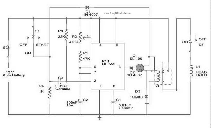
The circuit diagram for the automatic headlights turn-off circuit is presented here. This circuit can be installed in a car. The automatic headlights turn-off circuit is designed to enhance vehicle safety and convenience by ensuring that the headlights are automatically...
The following circuit illustrates how to build a variable DC power supply circuit. This circuit is based on the 7805 IC. Features: other output is ... The variable DC power supply circuit utilizing the 7805 integrated circuit (IC) is designed...
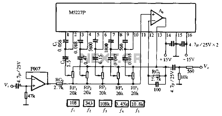
The M5227P is an application circuit designed for a graphic equalizer. Its control curve operates on a logarithmic frequency axis to represent the rate, requiring the same control curve pitch to ensure that all bands achieve maximum lift or...

To invoke the Spectrum +3 diagnostic routines, first reset the machine while holding the BREAK key down. This will bring up the test card display. Next, hold down the QAZMLP keys for a few seconds until the diagnostic title...
A simple transistor generator and transformer converts a 1.5V battery voltage to several hundred volts. This high voltage current then passes through a diode, which rectifies the current to DC. This DC current is stored in a relatively large...
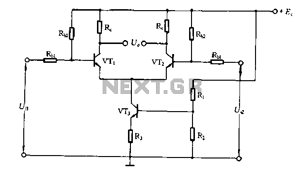
The differential amplifier circuit features a constant current source. The differential amplifier is a fundamental building block in analog electronics, utilized for amplifying the difference between two input voltages while rejecting any signals that are common to both inputs. Central...
Warning: include(partials/cookie-banner.php): Failed to open stream: Permission denied in /var/www/html/nextgr/view-circuit.php on line 713
Warning: include(): Failed opening 'partials/cookie-banner.php' for inclusion (include_path='.:/usr/share/php') in /var/www/html/nextgr/view-circuit.php on line 713