
RC relaxation type tone control circuit
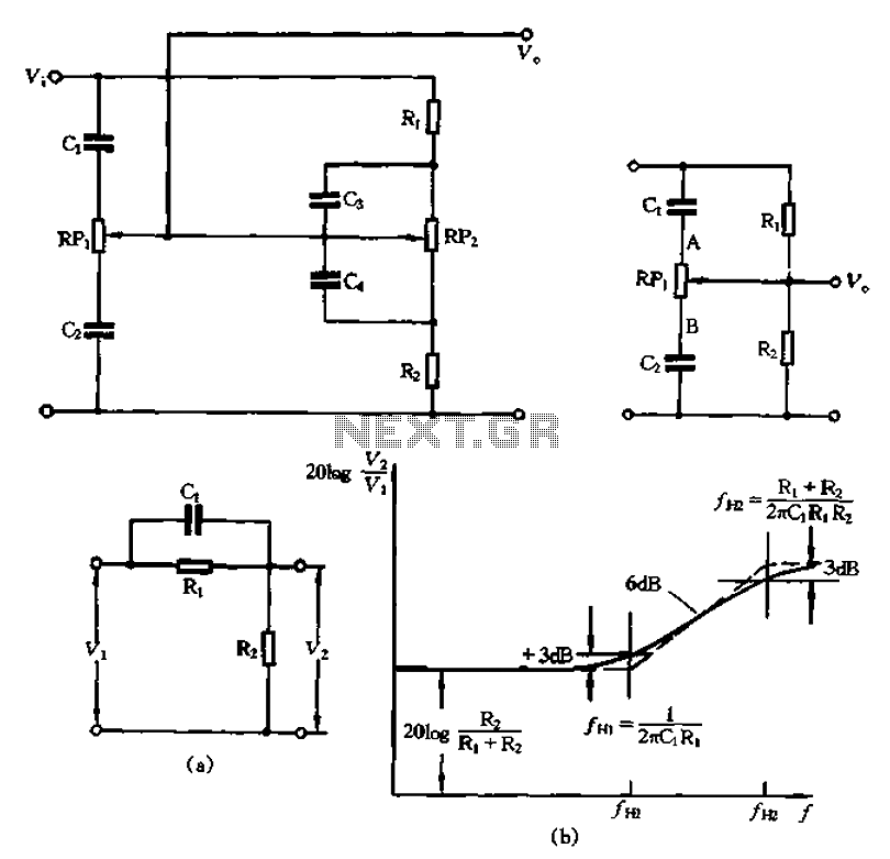
The treble control potentiometer circuit is designed to adjust high-frequency audio signals, enhancing the overall sound quality by allowing for specific frequency manipulation. The core components include a potentiometer, resistors, and capacitors, which work together to filter and amplify audio signals. The potentiometer (RPi) serves as the primary control element, enabling users to adjust the treble frequencies according to their preferences.
In this circuit, the interaction between the resistors and capacitors determines the frequency response. The larger capacitors (C3 and C4) effectively short-circuit high-frequency signals, allowing them to pass through while attenuating lower frequencies. This selective filtering creates a treble boost when the potentiometer is adjusted towards the high-frequency end. The relationship between resistance and capacitance is critical; as the resistance of RPi increases, the circuit behaves as an open circuit for lower frequencies, effectively removing bass and midrange components from the output.
The voltage gain characteristics of the circuit, as illustrated in Figure 1-58, demonstrate how the gain increases with frequency. The solid line in the figure indicates the actual gain behavior, while the dotted line provides a simplified approximation. The corner frequency, where the gain starts to flatten, is determined by the combined effects of the resistors and capacitors in the circuit.
Overall, this treble control circuit allows for precise audio adjustments, enabling users to enhance their listening experience by tailoring the high-frequency response to their specific needs. The careful selection of component values and the arrangement of the circuit elements ensure effective performance in various audio applications. Circuit shown in Figure 1-560 RPi is treble control potentiometer. Because C3, C4 is larger than cl, C2 capacity, so high-frequency signals, Pat, C4 can be regarded as a short circuit. So treble adjustment circuit can be simplified as in Figure 1-57. When the arm is moved to the top RPi point A, due RPi resistance is much greater than Rz, RPI, C2 branch can be regarded as open, so Figure 1-57 can be equivalent to FIG. 1-58 (a). Because cl terms of bass and midrange, can be regarded as open, so the frequency rate is relatively low, V2/V1 foot 2 Ri + 2 feet) 0 Figure 1-58 (a) for high frequency, q the capacitance is very small, high-frequency signal number can go through, and therefore, with respect to the volume treble bass t is increased.
when the frequency is high to a certain extent, ct can be regarded as a short circuit, V2 is almost equal to the o Figure 1 - VI 58 (b) to enhance the properties (a) circuit curve, solid line is the exact value of the control characteristics of the dotted line is an approximation. start turning the treble frequencies fHI 1/2 rrClRi, whereby point start, frequency per liter twice as high lift signal increases about 6dB;, annoyed by the lift characteristic curve into a flat corner frequency, H2 (Ri + Rz)/2, arRiRzC1 Assuming that Ri 10R2, then when, iO.
when the frequency increases 10 times larger than the transmission voltage relative increase 20dB (10 times).
Related Circuits
To measure the input impedance of an unknown circuit, first set the signal generator to a current source with a magnitude of 1 amp. A shunt resistor of 100 megohms is also required. This setup is beneficial for measuring...
This article explains the principle of the Audison LR604XR amplifier. The principle is straightforward; it is recommended to combine the text with a careful reading of the complete schematic. To fully understand this principle, it is advisable to review...
This circuit utilizes a single 555 Timer IC along with a small transformer to generate high voltage for testing zener diodes with voltage ratings up to 50VDC. The 555 timer operates in astable mode, with the output from pin...
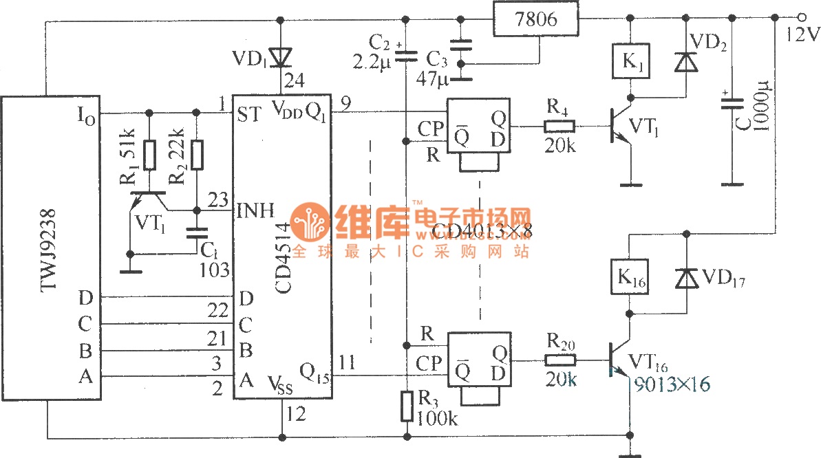
The Sixteenth Street control circuit consists of a secondary decoding output control circuit. Each output terminal of the sixteen decoding is connected to a bistable circuit made up of dual D flip-flops (CD4013). A DC relay is connected to...
This tutorial explains how to read the content of a microcontroller's flash memory. The source microcontroller reads the memory content and displays it on the LEDs. The content consists of the program stored in the microcontroller's memory. This step...

This circuit represents a remote control unit that utilizes radio frequency signals to operate various electrical appliances. The remote control unit features four channels, which can be expanded to twelve. This circuit stands out from similar designs due to...
Warning: include(partials/cookie-banner.php): Failed to open stream: Permission denied in /var/www/html/nextgr/view-circuit.php on line 713
Warning: include(): Failed opening 'partials/cookie-banner.php' for inclusion (include_path='.:/usr/share/php') in /var/www/html/nextgr/view-circuit.php on line 713