
2 Cell Lithium Ion Charger circuit
The circuit is designed to efficiently charge two lithium-ion cells connected in series. Each cell has a nominal voltage of 3.6 volts and a capacity of 1 Amp Hour, resulting in a total voltage of 7.2 volts for the series configuration. The charging system must incorporate a suitable charging IC that is specifically designed for lithium batteries, such as the TP4056 or a similar device, which provides constant current and constant voltage charging profiles.
The circuit should include a power source capable of supplying the required voltage and current to the charging IC. A common choice is a USB power supply, which typically provides 5 volts. To accommodate the series configuration of the batteries, a boost converter may be necessary to step up the voltage from the USB supply to the required charging voltage of approximately 8.4 volts (the full charge voltage for two lithium cells in series).
Protection features are critical in lithium battery charging circuits to prevent overcharging and ensure safe operation. The circuit should include a battery management system (BMS) that monitors voltage and current levels, disconnecting the charger if the voltage exceeds safe limits. Additionally, temperature sensors may be integrated to prevent overheating during the charging process.
To enhance the user experience, the circuit may also include LED indicators to show the charging status, providing visual feedback on whether the batteries are charging, fully charged, or if there is a fault condition. Proper layout and thermal management should be considered to ensure that components operate within their safe limits, maintaining reliability and safety throughout the charging cycle.
Overall, this circuit serves as a compact and efficient solution for charging lithium cells in portable electronic devices, ensuring performance and safety in the charging process.This circuit was build to charge a couple series Lithium cells (3.6 volts each, 1 Amp Hour capacity) installed in a portable transistor radio.. 🔗 External reference
Related Circuits
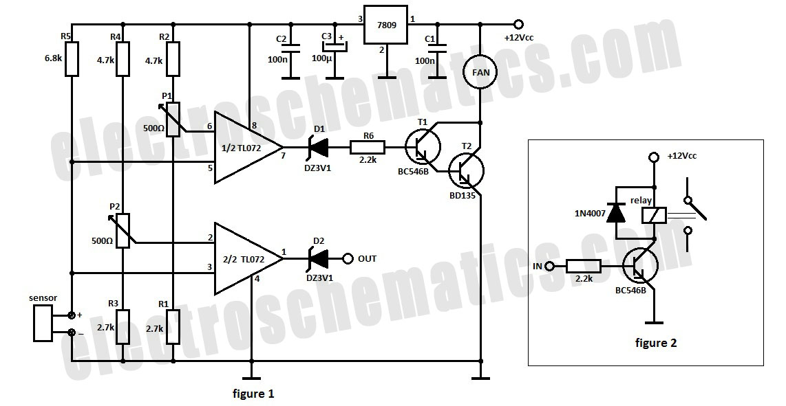
The automatic fan controller circuit depicted in the schematic features two comparators with distinct triggering points that can be adjusted independently. LM135 or... The automatic fan controller circuit is designed to regulate fan operation based on temperature variations. It employs...
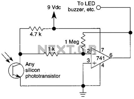
This circuit represents one of the simplest infrared (IR) receivers that can be constructed. The components are inexpensive, the layout is not critical, and a 9-V battery provides a long operational life. The described IR receiver circuit typically consists of...

This is a circuit for Closed-Loop Automatic Power Control for RF Applications. The circuit utilizes a log detector (AD8318) and a variable gain amplifier (VGA) (ADL5330). The Closed-Loop Automatic Power Control (APC) circuit is designed to maintain a consistent output...

An AC-coupled unity gain voltage follower operating on a single supply is illustrated. The voltage divider network consisting of resistors R1 and R2 provides a DC voltage equal to half the supply voltage to the non-inverting input of the...
This circuit diagram for a 12V inverter is simple to construct and utilizes inexpensive components that many electronics hobbyists may already possess. While it is feasible to create a more powerful circuit, the complexity arises from managing the significant...
The input signal is applied to a gate G and then to a counter for a precise period of time. After this period, the input signal is stopped for a while, and then the cycle is repeated. During the...