
live line detector indicator circuit schematic
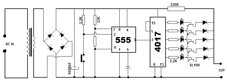
The described circuit utilizes a 4017 decade counter integrated circuit to detect the presence of an alternating current (AC) signal induced via capacitive coupling. The circuit is designed to operate in proximity to live conductors, allowing for non-invasive detection of electrical signals without direct contact.
The core of the system is built around the 4017 IC, which is a decade counter that counts from 0 to 10. The input to the counter is derived from the capacitive coupling of the probe to the live conductor. As the unit approaches an AC source, the capacitive coupling generates a small AC voltage at the input of the 4017, which triggers the counting mechanism. The frequency of the AC mains supply is typically 50Hz, and the 4017 divides this frequency by ten, resulting in a counting frequency of 5Hz. This output is used to drive an LED indicator, which flashes at this rate, providing a visual indication of the presence of the live conductor.
When the unit is moved away from the live conductor, the capacitive coupling diminishes, leading to the cessation of the input signal to the 4017. Consequently, the counter stops counting, and the LED indicator remains off, indicating that there is no longer a live signal detected in the vicinity.
The design of this circuit emphasizes safety and non-contact measurement, making it suitable for applications where direct electrical contact is impractical or dangerous. Additional components may include resistors to limit current to the LED and capacitors to filter the signal, ensuring stable operation and accurate detection. Proper layout and shielding techniques may also be employed to minimize interference and enhance the sensitivity of the probe.If the unit is brought close to a live conductor (insulated, and even buried in plaster) capacitive coupling between the live conductor and the probe clocks the counter, and causes the LED to flash 5 times per second, because the 4017 IC divides the mains 50Hz frequency by 10. When remote from a live line, the unit stops counting, the LED resulting permanently off.. 🔗 External reference
Related Circuits

The adjustable power supply can be reconfigured by changing the value of V2 and enhancing other components as needed. The output voltage is calculated using the formula Vnm = 1.25 (1 + R2/R^). Additionally, R2 can be modified as...
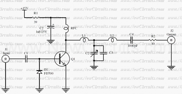
The RF circuit is a C-Class power amplifier. It is used in the last stage of transmitters. Its maximum power output is about 1 Watt. The circuit can be used in 3 frequency ranges: 30-100-200 MHz. More: The P-Out...
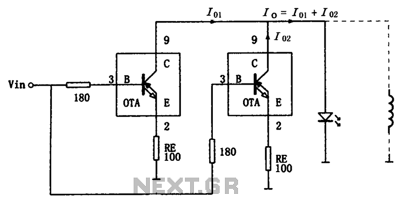
The high-speed parallel current drive circuit utilizes the OPA660 operational transconductance amplifier (OTA). An input signal, Vin, is connected to a 180-ohm resistor equivalent device at the base (pin 3) of the OPA660. The collector (pin 8) is directly...
This circuit utilizes a standard loudspeaker, enabling it to function as a microphone. It allows for the use of an inexpensive loudspeaker in this capacity. Sound waves impacting the speaker cone result in variations in the voice coil. The...
These ultrasonic circuits are all quite old: my notes date them at mid-70s so they don’t use ICs. Nevertheless there are several places where an op-amp would possibly simplify things. Despite their age I hope they are of interest:...
Battery eliminators are circuits that create a DC power supply from AC mains. Essentially, battery eliminator circuits consist of a step-down transformer, rectifier, and voltage regulator. A simple circuit of a multipurpose battery eliminator features various output voltage ranges...