
AD589-Dual Supply LVDT Signal Conditioner Design Procedure
The Linear Voltage Differential Transformer (LVDT) is a highly precise sensor commonly employed for measuring linear displacement. It operates based on the principle of electromagnetic induction, where a primary coil generates a magnetic field that induces voltages in two secondary coils. The differential voltage between these coils is proportional to the position of a movable core within the transformer, enabling accurate position sensing.
The AD589 integrated circuit is designed to facilitate the signal conditioning necessary for LVDT applications. This precision voltage reference provides a stable output voltage, which is essential for ensuring the accuracy of the LVDT measurements. The AD589 features low noise and low drift characteristics, making it suitable for high-precision applications where environmental factors may influence the sensor's performance.
In a typical LVDT application circuit, the LVDT is connected to the AD589 to amplify the differential output voltage. The output from the AD589 can be further processed using an analog-to-digital converter (ADC) for digital signal processing. This integration allows for the development of sophisticated control systems capable of providing real-time feedback on position changes, which is vital in various automation and robotics applications.
The combination of LVDT technology and the AD589 integrated circuit results in a robust solution for linear position sensing, offering high accuracy, reliability, and stability in diverse industrial environments.LVDT (linear voltage differential transformer) is widely used as linear position sensor. AD589 integrated circuit provides a complete solution for LVDT.. 🔗 External reference
Related Circuits
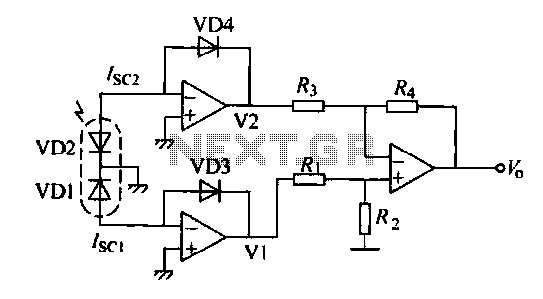
The operation of a semiconductor color sensor can be summarized as follows. The figure illustrates the spectral response curve of two photodiodes that intersect at a specific wavelength. When light of this wavelength is incident on the photodiodes, the...
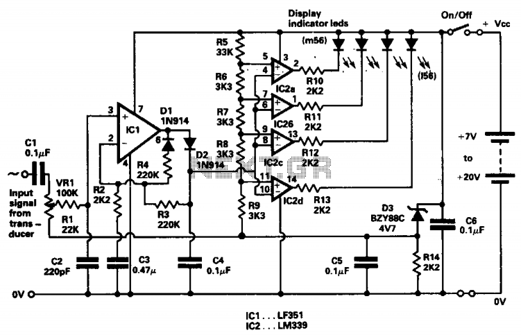
The indicator was designed to display the peak level of small AC signals from various transducers, including microphones, strain gauges, and photodiodes. The circuit responds to input signals within the audio frequency spectrum, specifically from 30 Hz to 20...
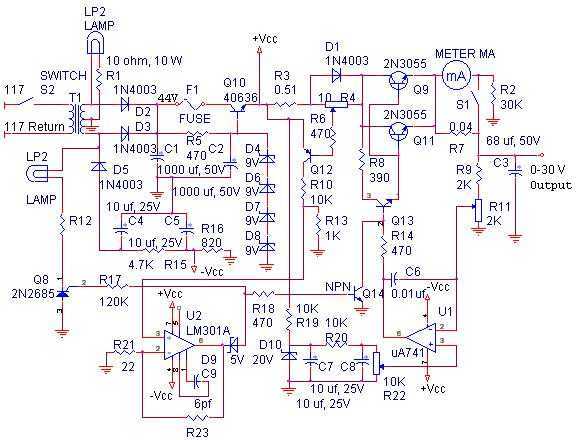
The linear power supply, shown in the schematic, provides 0-30 volts, at 1 amp, maximum, using a discrete transistor regulator with op-amp feedback to control the output voltage. The supply was constructed in 1975 and has a constant current...
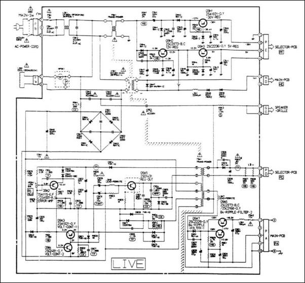
A 12V switching power supply schematic has been observed to generate significant heat, which has prompted discussions among users in prominent forums, such as dp. The 12V switching power supply is a crucial component in various electronic applications, providing...
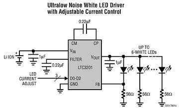
The LTC3201 contains overtemperature protection and can survive an indefinite output short to GND. Low external parts count (one small flying capacitor and three small bypass capacitors) and small MSOP-10 package size make the LTC3201 ideally suited for space...
In this small switching power supply, a Schmitt trigger oscillator is used to drive a switching transistor that supplies current to a small inductor. Energy is stored in the inductor while the transistor is on, and released into the...