
Switching Power Supply 14V
This switching power supply circuit operates by utilizing a Schmitt trigger oscillator to generate a square wave signal that drives a switching transistor, typically a MOSFET or bipolar junction transistor (BJT). The transistor alternately connects and disconnects the inductor to the supply voltage, allowing energy to be stored in the magnetic field of the inductor when the transistor is in the 'on' state.
When the transistor turns 'off', the magnetic energy stored in the inductor is released, causing a voltage spike. This spike is crucial as it allows the inductor to transfer energy to the load. The output voltage can be regulated based on the load resistance, which influences the amount of current flowing through the inductor and subsequently the voltage across the load.
A zener diode is incorporated into the circuit to provide voltage regulation. When the output voltage reaches approximately 14 volts, the zener diode becomes reverse-biased and effectively stops the Schmitt trigger oscillator from oscillating, thereby preventing further increases in output voltage. This feedback mechanism ensures that the power supply maintains a stable output voltage, protecting connected components from overvoltage conditions.
To adjust the output voltage levels, a voltage divider can be implemented, allowing for fine-tuning of the input to the zener diode. By changing the resistor values in the divider, various output voltages can be achieved, making the power supply versatile for different applications.
The efficiency of the power supply is approximately 80%, which is a significant factor in its design. Utilizing a high Q inductor minimizes energy losses due to core losses and skin effect, contributing to the overall performance of the circuit. This efficiency rating is essential for applications where power conservation is critical, such as in battery-operated devices or compact electronic systems.
Overall, this small switching power supply design showcases a practical application of basic electronic principles, combining oscillation, energy storage, and voltage regulation to achieve a reliable power source.In this small switching power supply, a Schmitt trigger oscillator is used to drive a switching transistor that supplies current to a small inductor. Energy is stored in the inductor while the transistor is on, and released into the load circuit when the transistor switches off.
The output voltage is dependent on the load resistance and is limited by a zener diode that stops the oscillator when the voltage reaches about 14 volts. Higher or lower voltages can be obtained by adjusting the voltage divider that feeds the zener diode. The efficiency is about 80% using a high Q inductor. 🔗 External reference
Related Circuits
This module is an essential addition to the Modular Preamplifier Control Center when more than two sources need to be connected to the preamplifier chain. Four high-level inputs can be selected using SW1 and routed to the output. The...
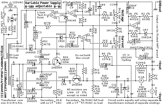
A reverse-engineered circuit diagram of a high-end commercial variable laboratory power supply. This unit is constructed using a standard operational amplifier and readily available components. While the design employs a single transformer with dual output windings, it can also...
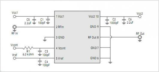
The WSH412 is designed to integrate a Hall sensor with complementary output drivers and a frequency generator on a single chip. It is suitable for applications such as speed measurement, revolution counting, positioning, and DC brushless motors. The device...
The wide variety of automotive motor drivers, including those used for HVAC (heating, ventilation, and air conditioning), headlamp, seat positioning, window, and mirror applications, necessitates circuits that perform more than just switching the motor on and off. The drivers...
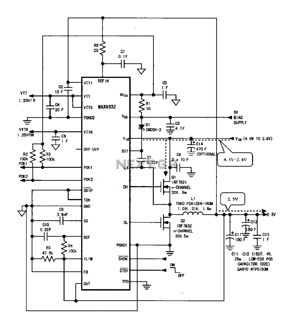
DDR memory power supply circuit. This circuit illustrates the power supply configuration for notebook DDR memory, utilizing the MAX8632 power control circuit chip. The power supply terminal VDD is connected to the voltage detection point 1. The battery DC...
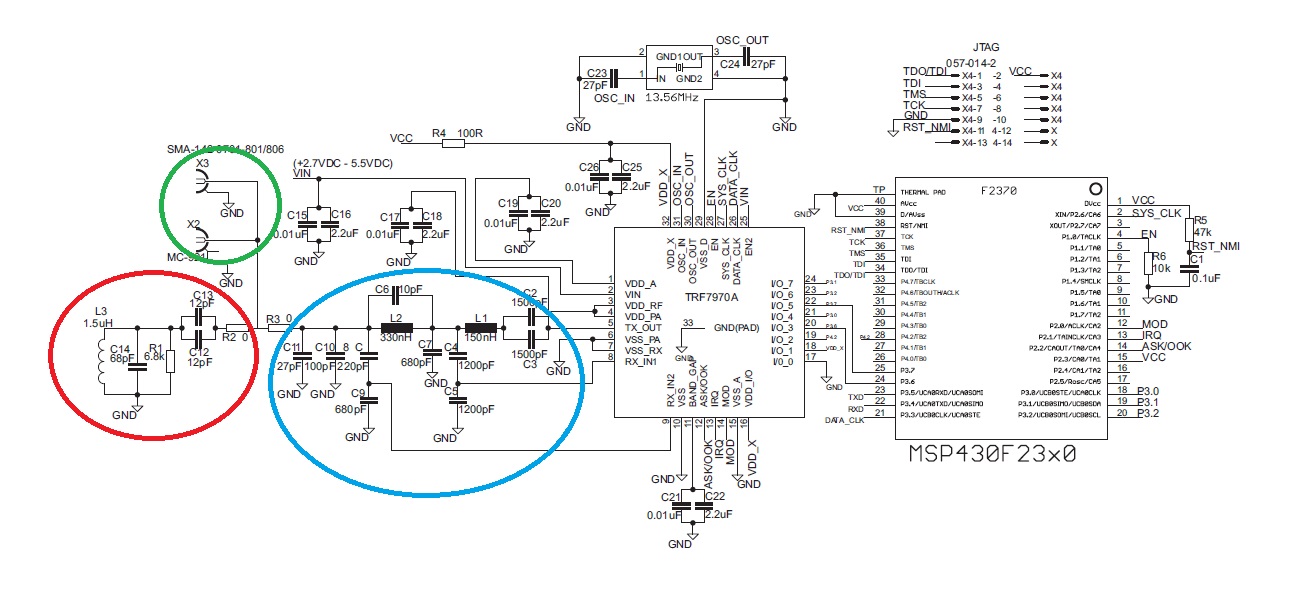
The "green area" is designated for the placement of the TRF7970A's antenna, which should be connected between two 0-ohm resistors. The antenna can be constructed step by step following the guidelines in the document "Antenna Matching for the TRF7960...