
Bar-graph indicator for ac signals

The indicator circuit is a fundamental tool in audio and signal processing applications, allowing for the visual representation of signal levels. The design typically incorporates an operational amplifier (op-amp) configured as a peak detector. This configuration captures the peak voltage of incoming AC signals and holds that value for a brief period, enabling an easy readout on a display element, such as an LED or an analog meter.
Key components include the op-amp, which amplifies the input signal, and a diode that rectifies the AC signal to DC for peak detection. A capacitor is used to smooth the output, providing a stable reading that corresponds to the peak level of the input signal. The variable resistor VR1 serves as a gain control, allowing for calibration to accommodate different signal strengths. By adjusting VR1, the circuit can be fine-tuned to ensure accurate peak level readings across a range of input voltages.
The frequency response of the circuit is crucial, particularly in applications involving audio signals. The specified range of 30 Hz to 20 kHz covers the majority of human hearing, making this indicator suitable for audio engineering tasks. The extended response up to 40 kHz may be beneficial in applications involving ultrasonic signals or high-frequency transducers.
Calibration of the circuit is an essential step to ensure accurate readings. By applying a known input signal and adjusting VR1, the user can set the indicator to reflect true peak levels, compensating for any variations in component tolerances or environmental factors. This calibration process enhances the reliability of the indicator in practical applications, ensuring that it meets the necessary performance standards for professional use.
In summary, this peak level indicator circuit is a versatile and essential tool for monitoring small AC signals from various transducers, providing a clear and accurate representation of signal levels across a wide frequency range.Indicator was designed for displaying the peak level of small ac signals from a variety of transducers including microphones, strain gauges and photodiodes. The circuit responds to input signals contained within the audio frequency spectrum, i.e., 30 Hz to 20 kHz, although a reduced response extends up to 40 kHz.
Maximum sensitivity for the component values shown, with VR1 fully clockwise, is 30 mV peak-to-peak. The indicator can be calibrated by setting VR1 when an appropriate input signal is applied.
Related Circuits
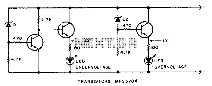
This circuit will activate the LED when the monitored voltage drops below the values determined by the Zener diodes D1 and D2. The circuit utilizes Zener diodes to establish reference voltage levels, which are critical for monitoring voltage thresholds. The...
A peak level indicator is a device that signals when a signal surpasses a specific maximum value. It proves to be particularly beneficial in applications such as tape recorders and mixing consoles. A crucial requirement for a peak level...
This is the most simple phone busy indicator is possible with only three parts. Connect the circuit so that the green light illuminates when the line is free. If the receiver than the hook, the green LED light is...
This circuit clearly indicates the supply voltage level in a larger device. When the indicator receives a stable 12 volts, LED1 emits a steady yellow light. If the input voltage drops below 11 volts, LED1 begins to blink, with...
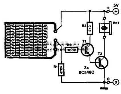
Running a bath can lead to a minor domestic disaster if the taps are forgotten. This indicator activates an audible buzzer when a specific water level is reached. The water sensor and the buzzer driver circuit are integrated on...
Game Show Indicator Lights (Who's First) Circuit The circuit below activates a light corresponding to the first of several buttons pressed in a Who's First game. Three stages are shown, but the circuit can be extended to include additional...