
AD9284 default mode problem

The circuit configuration involves the integration of the AD9284 analog-to-digital converter (ADC) with the ADL5380 demodulator. The AD9284 is designed for high-speed applications and requires proper interfacing to ensure optimal performance. The demodulator outputs I and Q signals, which are essential for phase detection in communication systems. When interfacing the demodulator with the ADC, it is critical to manage the common mode voltage levels to prevent distortion and ensure accurate digital representation of the analog signals.
The lack of a reference voltage interface can lead to improper ADC operation, as the ADC requires a defined common mode voltage at its inputs for correct sampling. The suggested approach is to implement a voltage divider that can scale the common mode voltage from the demodulator down to the required 0.9V level for the ADC inputs. This can be achieved by using resistors to create a voltage divider network, ensuring that the impedance seen by the ADC is appropriate for its specifications.
In practical terms, the output from the ADL5380 should be AC-coupled to the ADC input via a capacitor to block any DC component while allowing AC signals to pass. The inclusion of series resistors can help match the impedance and reduce reflections, which is particularly important in high-frequency applications.
The design must also consider the insertion loss introduced by the components used in the signal path. Careful selection of component values and types, as well as layout considerations, will play a crucial role in maintaining signal integrity. The final schematic should reflect these considerations, ensuring that both the I and Q outputs are correctly interfaced with the ADC while maintaining the necessary common mode voltage levels for reliable operation.Using AD9284 with the interface of adl5380 demodulator. I tried to work in default mode of AD9284. I have checked I and Q outputs of demodulator and everything was fine there. When i checked digital outputs of AD9284, I could not see the desired output. So, AD9284 seem to be not working properly. Second, there is not an Reference voltage interface in between demodulator and ADC. Actually output of the demodulator is connected to the ADC through a capacitor and I think that this type of a usage should be OK. Still, I am not sure that this may cause some serious problems. it sounds like you shouldn`t have an issue with the common mode voltage on the output of the ADL5380 if you have DC blocking caps.
Do you have the common mode voltage (CMV) connection for the AD9284 It should be connected similar to the below schematic. Perhaps you could send me an IM with your schematic so I could take a look and review it. Thank you for your support. I think i may have interface problem between demodulator and adc. Interface is at attachment. I did not use Vcm voltage in my interface circuit. I just connected it to ground by a decoupling capacitor. If you are just using the topology you have shown in your last reply, it does not appear that you have provided the common mode voltage to the ADC inputs.
In order to operate correctly, the 0. 9V common mode voltage needs to be applied to the Vin+ and Vin- inputs. You have the option of using a voltage divider topology in the circuit between the ADL5380 and the ADC, but you have tradeoffs to consider on the performance (see page 22 of the ADL5380 datasheet). In order to keep insertion loss down and have an easier translation to the 0. 9V for the ADC, the lower common mode output voltage of the ADL5380 would work best, but this has the tradeoffs listed on page 22 of the ADL5380 datasheet.
Ideally, you would have the network I`ve shown in my other reply, but you could make it work with something like the topology below (if you replace the first series caps in your circuit with series resistors and then split the last differential resistor into two single ended resistors). The circuit below creates a 200 ohm differential load impedance and voltage divides a 1. 6V common mode down to 0. 9V for the ADC. 🔗 External reference
Related Circuits
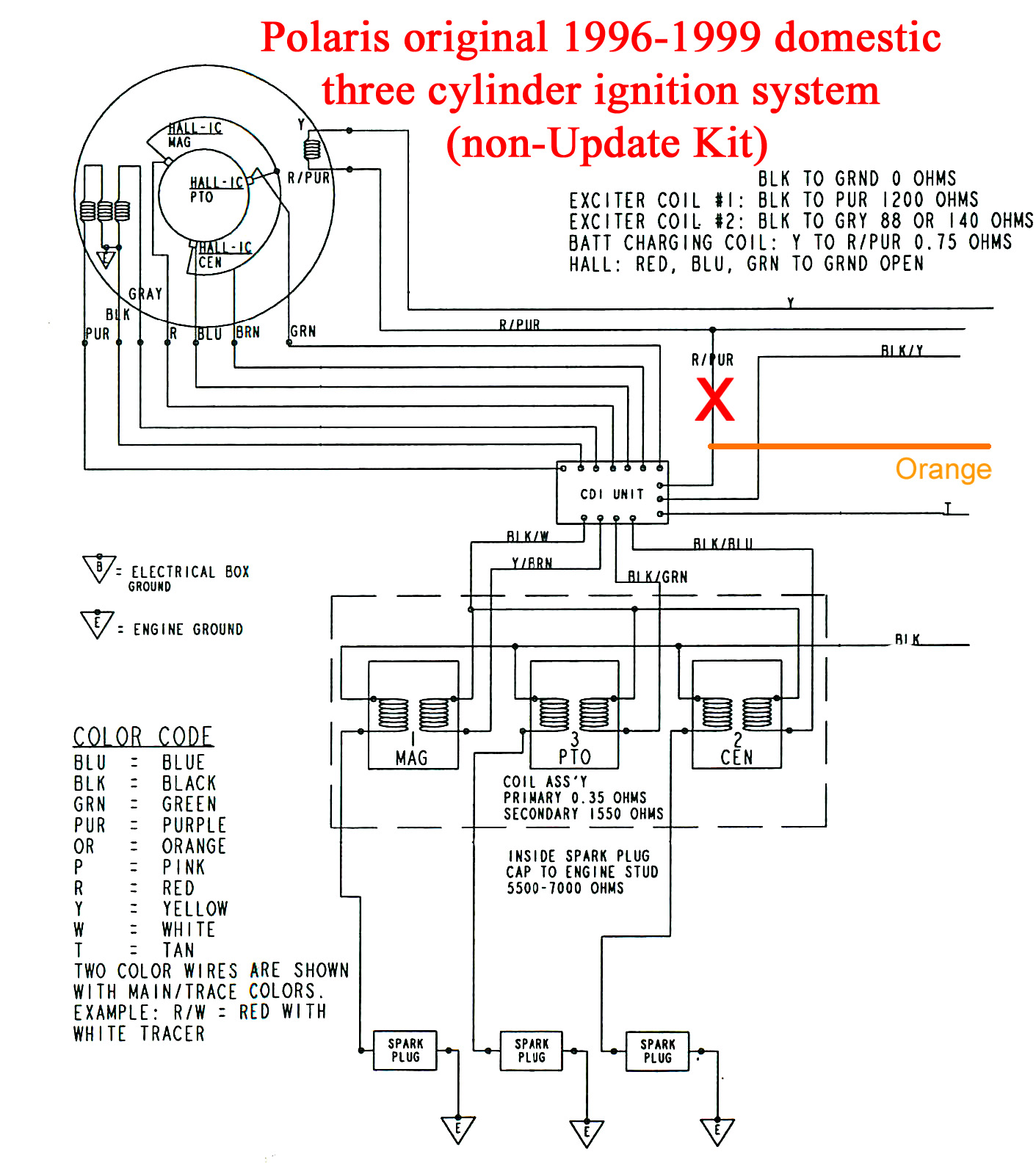
A Polaris Jet Ski Model SLTX 1050 with a 3-cylinder engine from the year 1998 was operational until a piston failure occurred. The engine was removed, rebuilt, and reassembled, but it fails to start due to a lack of...
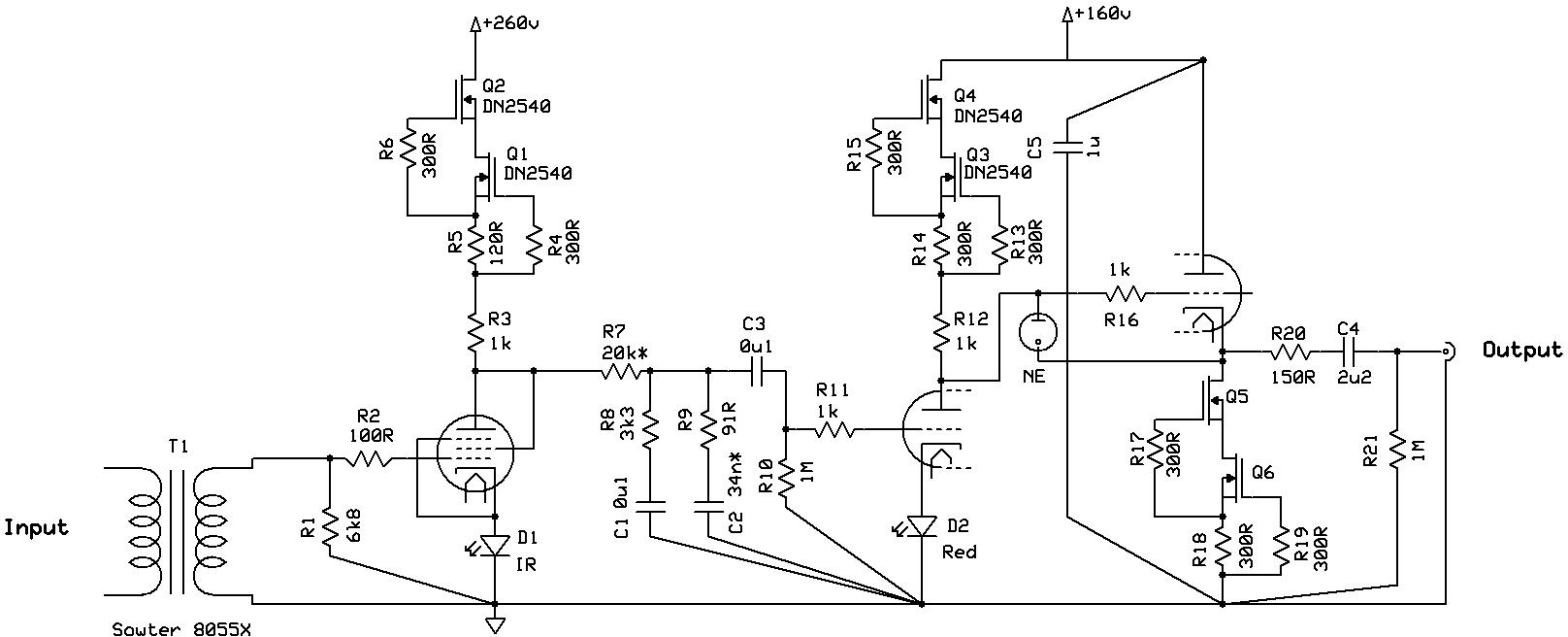
Even if it was not read thoroughly, it is a nice design with almost enough transformers, but certainly not enough shunt regulators. The circuit design under consideration features a configuration that includes several transformers, which are essential for voltage transformation...
The dashboard illumination dims when the vehicle's lights are activated, which is normal during daylight. The dashboard assembly was removed and sent to a local Corvette specialist for repair. Upon follow-up with the dealer, it was reported that the...
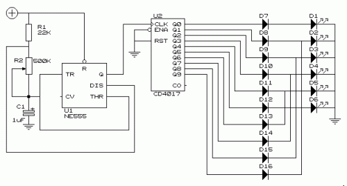
This simple circuit drives six LEDs in a "Knightrider scanner mode." Power consumption primarily depends on the type of LEDs used, especially if a 7555 (555 CMOS version) is utilized. The circuit operates by sequentially illuminating the LEDs to create...
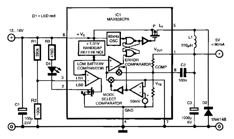
The circuit is straightforward due to the use of the MAX638CPA 5V CMOS Step Down Adjustable Switching Regulator IC. This IC converts an input voltage of 12 to 16 VDC into a stable 5VDC output. The circuit requires only...
This page provides information about the T1-rate modem designed in 1993. It is important to note that this modem is primarily useful for licensed amateur radio operators and is not suitable for general use unless operated over wires, as...