
Utah T1-Rate Modem

This T1-rate modem is designed to operate within specific parameters suitable for amateur radio applications. The baseband modem architecture allows for efficient data transmission over a medium characterized by a bandwidth of 1.5 MHz, which is essential for effective communication. The modem's capability for full-duplex operation enables simultaneous transmission and reception of data, enhancing its functionality in point-to-point links.
The construction of this modem requires careful attention to detail, particularly in the selection and configuration of components. The use of off-the-shelf parts simplifies sourcing and assembly, making it accessible to hobbyists and engineers alike. The need for precise adjustments and understanding of the circuitry is critical, as the modem is not designed for novice builders.
The communication setup described involves crossband operation, utilizing FM video transmitters and receivers operating on different frequency bands (23 cm and 13 cm). This configuration allows for effective long-range communication, provided that there is a clear line of sight and adequate antenna gain. The specified gain of 10-13 dB and the use of 1 watt of transmit power contribute to the robustness of the link over a distance of 30 miles.
In terms of signal processing, the modem's baseband output is critical for ensuring that the transmitted signal occupies the designated bandwidth. By adjusting the transmit deviation, the modem can maintain an occupied bandwidth of approximately 3 MHz, which is crucial for minimizing interference and optimizing signal clarity. The integration of a demodulator/slicer system, particularly the use of the Motorola MC13055, allows for effective data recovery and clock synchronization, which are essential for maintaining data integrity during transmission.
Overall, this T1-rate modem represents a practical solution for amateur radio operators looking to establish reliable digital communication links. Its design, while not optimized for all scenarios, provides a solid foundation for experimentation and improvement, encouraging users to refine the system further based on their specific needs and experiences.This is a "quick-and-dirty" page that I set up to describe the T1-rate modem that I designed several years ago (in 1993, actually. ) Let me point out that unless you are going to use this on wires, this modem is absolutely useless to anyone other than licensed amateur radio operators: It does NOT intrinsically lend itself to FCC part 15 operation.
You are free to experiment with this design as much as you want. All I ask is that you do so legally and, if you make any improvements and refinements, you let me know what you have done so that I can share them with others as well. It is not plug-and-play. What you get are schematics and a description. If you are intimidated when it comes to building things from scratch, then maybe you need to pick another project (or find a friend to help you build it.
) This modem is not the ultimate in optimized design. This is a somewhat refined prototype that DOES work as advertised, as long as it is adjusted correctly by someone who understands what they are doing. This modem uses easily obtainable, off-the-shelf parts that should be available, through only modest effort, anywhere in the world.
I am absolutely confident that this design can be improved upon. This is a baseband modem. That is, given a medium that has a bandwidth of 1. 5 MHz (starting at a few 10`s of hertz) and is reasonably well-behaved in terms of amplitude and phase, this modem will push data across it. This is a full-duplex modem (well actually, if you only ever wanted to send data in one direction, that would be fine, too.
) Clock acquisition takes a significant fraction of a second, so you will want to have a path that is there all of the time. Suppose you have wideband FM transmit/receive radio set (Amateur Television FM transmitter and receiver are almost ideal, except that the receiver`s IF bandwidth will be wider than necessary.
) As long as you are on the 33cm Amateur band (or higher) you can legally use this (in the U. S. , at least. ) Now, let`s suppose that we want to link two sites that are, say, 30 miles apart with a full-duplex T1-rate point-to-point link. To simplify matters, let`s go crossband, so on my end I have a 23cm FM video transmitter and a 13cm FM video receiver, and the other end has the opposite- a 13cm FM video transmitter and 23cm FM video receiver.
If the antennas are 10-13 db gain and there is 1 watt of transmit power (overkill, actually. ) and a clear line-of-sight path, we`ll be fine. Keep in mind that we`ve modified the receivers to have a 5 MHz IF bandwidth or so to better match our actual occupied bandwidth. (If you didn`t narrow the bandwidth, it would still work, but you`d have more possibility of adjacent-channel interference issues, plus lower effective receive system sensitivity.
) The baseband output of the modem is simply fed into the transmitter input and the transmit deviation is adjusted so that the occupied bandwidth is on the order of 3 MHz or so. On the receive side, the recovered baseband output is fed into the modem, the VCXO on the clock recovery is centered, the data-sense jumper is set for proper polarity, and we are ready to go as soon as we do the same for both ends.
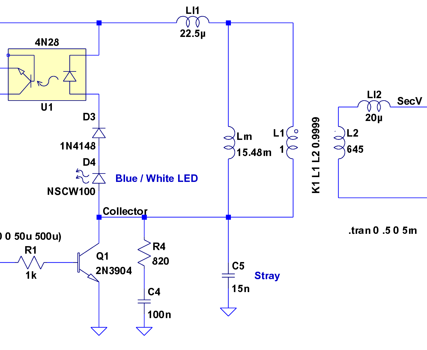
The tricky part is to find some sort of box that can handle T1-rate data. One such box that we have used is the Gracilis Packeten. The modem supplies the transmit clock to the Packeten, and it reconstructs and supplies the receive data clock to the Packeten as well. Well, you were already pre-warned that all you get are some schematics. The schematic shows an integrated demodulator/slicer system. What`s that A demodulator I thought you said that this was a baseband modem Well, it is. except that the radio that we initially tested it on (when I drew the schematics) did not have a demodulator, so I used a Motorola MC13055 data receiver IC for its discriminator, and used the built-in comparator/slicer to get a "raw data" stream for clock recovery.
🔗 External reference
Related Circuits
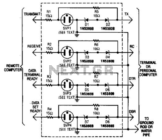
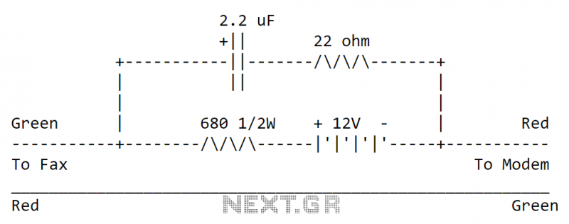
This modem/fax protector can be utilized in telephone-line connections between a PC or a terminal and a remote computer. In this circuit, the surge voltage protectors (SVPs) are rated at 230 V. Additionally, a proper grounding is essential for...
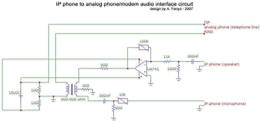
The transformer is a 600:600 ohm transformer, also referred to as a 1:1 ratio 600 ohm transformer. It has approximately the same number of turns on both the primary and secondary coils and is optimized for operation at a...
The TCM3105 FSK modem chip from Texas Instruments enables the construction of a modem compatible with Bell 202 or CCITT V23 standards. This modem circuit can transmit data at baud rates of 75, 150, 600, and 1200, and receive...
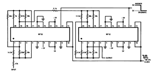
Later, there will be applications including a Basic Circuit Description, Block Diagram of the MF10, Programmable Dual Clock Generator, Butterworth Lowpass Filter, MF10 as an Input Filter and Sample/Hold, Generating Quadrature Sine Waves, and the Non-Inverting Integrator used in...
A project is being developed involving GSM technology, with the objective of detecting key presses on the remote side during an active call. An attempt is being made to utilize a DTMF decoder circuit connected to the speaker output;...
The circuit can be easily built to a small plastic box with telephone connectors in both ends. The circuit takes about 10-20 mA current, so if the circuit is not in use all the time it is best to...