
Adaptor for the Dreamcast serial port
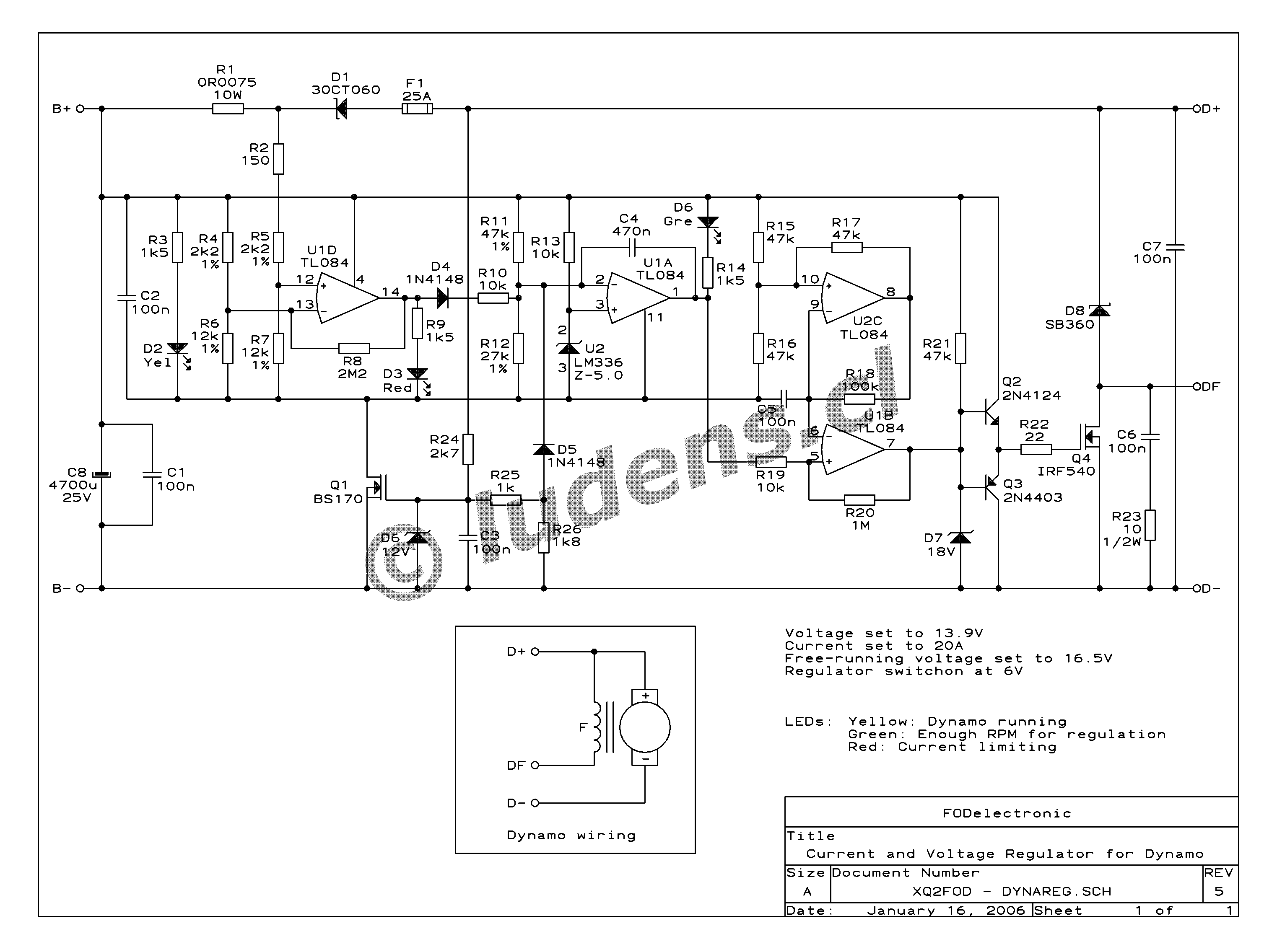
The Dreamcast serial port adaptor is an essential interface for connecting the Dreamcast console to a computer for various applications, including data transfer and debugging. The design utilizes a MAX voltage converter, specifically the MAX232 or a similar variant, which is crucial for level shifting between the low-voltage CMOS logic levels of the Dreamcast and the higher voltage levels of standard RS232 communication.
The schematic of the adaptor includes the following components:
1. **MAX Voltage Converter**: This chip is responsible for converting the 3.3V signals from the Dreamcast to the +/-12V signals required by RS232. It typically includes internal capacitors that are used for voltage doubling and inverting.
2. **9-pin DSUB Connector**: This connector serves as the interface for connecting the adaptor to the computer's serial port. The pinout must be configured correctly to ensure that the signals are transmitted and received properly.
3. **Capacitors**: The MAX voltage converter requires external capacitors for proper operation. Common values include 1µF and 10µF capacitors that are connected to the appropriate pins of the MAX chip to facilitate the voltage conversion process.
4. **Power Supply**: The circuit must be powered appropriately, typically from the Dreamcast’s power supply, ensuring that the voltage levels remain stable during operation.
5. **Signal Lines**: The adaptor will include signal lines for TX (transmit), RX (receive), and ground connections. Proper routing of these lines is essential to avoid signal integrity issues.
6. **PCB Layout**: A printed circuit board (PCB) can be designed to house all components in a compact manner, with careful consideration of trace widths and lengths to minimize interference and ensure reliable communication.
When building this adaptor, attention must be paid to the pin configurations of both the Dreamcast serial port and the DSUB connector to avoid potential damage to the devices. Testing the circuit with a multimeter before connecting to the Dreamcast or computer is recommended to verify proper voltage levels and continuity.
This adaptor can be a valuable tool for developers and enthusiasts looking to explore the capabilities of the Dreamcast console and integrate it with modern computing environments.This page describes how to build an adaptor for the Dreamcast serial port that will allow you to connect it to any computer using a standard 9-pin DSUB connector. The main component is a MAX voltage converter, since the Dreamcast serial port uses CMOS (3.3V) voltage levels, whereas normal RS232 uses +/-12V levels.
This serial adaptor has been designed, built and tested by me. It works prefectly for me, but I will not be held responsible if it fries your DC, your computer, and/or your hair. Also, please note that you will probably only find this interface usable if 🔗 External reference
Related Circuits
This temperature controller functions as a pulse snatching device, enabling it to operate at its own speed and activate at the zero crossing of the line frequency. The zero crossing activation minimizes the generation of line noise transients. A...
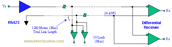
The EIA/TIA-423 Unbalanced (Single-Ended) interface specifies a single, unidirectional driver with multiple receivers (up to 10). It outlines the electrical characteristics of the unbalanced voltage digital interface circuit, typically implemented in integrated circuit technology, which can be used for...
This circuit is mainly intended to provide common home stereo amplifiers with a microphone input. The battery supply is a good compromise: in this manner the input circuit is free from mains low frequency hum pick-up and connection to...
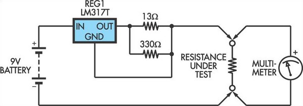
This adapter circuit functions as a 100mA constant current source. It is connected across a low-value resistor, the resistance of which is to be measured, and the resulting voltage drop can then be assessed using a digital multimeter (DMM)....
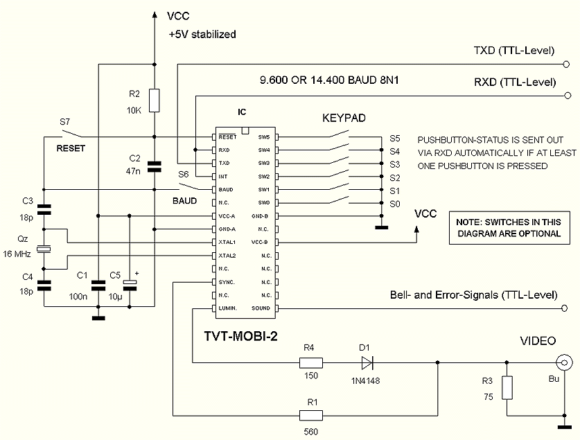
The TVT-MOBI-2 will initially display a static image and will not respond to data from its serial interface, except for one function. The internal clock can be set by providing a date and time value, allowing it to calculate...
Tutorial on interfacing the 20x4 LCD module to the PC parallel port. The interfacing of a 20x4 LCD module with a PC parallel port involves several steps, which include hardware connections, software setup, and programming. The 20x4 LCD module is...