
Adding a Mono Mic or Tape Level Output to the 302
The circuit described integrates a mono microphone-level output into an existing audio system, specifically designed for the 302 model. The primary function of this modification is to facilitate the connection of devices that require a mono mic-level input, such as transcription recorders and wireless transmitters.
The circuit operates by summing the left and right tape outputs, which are typically at line level, and attenuating this combined signal to a mic-level output. The attenuation is set to -55 dB, which is standard for microphone inputs, ensuring compatibility with various audio devices that expect a lower input level.
The design includes a summing amplifier configuration that takes the left (L) and right (R) outputs from the tape deck. These signals are fed into a resistor network that combines them into a single output. The resistors are selected to achieve the desired attenuation while maintaining a balanced input from both channels.
Furthermore, the circuit design allows for the tape output to remain available for other auxiliary inputs, which is crucial for setups where multiple devices may need to access the original tape signal without interference.
In scenarios where it is necessary to keep the output at tape level, the circuit can be adjusted to bypass the attenuation stage, allowing users to select between a mono output at mic level or a stereo output at tape level. This flexibility is particularly useful for live sound environments or recording applications where the audio routing may change frequently.
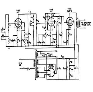
The accompanying wiring diagram is essential for accurately implementing this modification, providing clear connections for the tape outputs and the summing circuit. Properly following this schematic will ensure that the mono mic-level output functions effectively while maintaining the integrity of the original tape output for other uses.The addition of a mono mic-level output to the 302 is a useful addition for feeding transcription recorders, Comtek transmitters, and other inputs. The diagram below illustrates the proper wiring to add a mono mic-level output from the tape level output.
This circuit sums the left and right tape outputs and attenuates the summed signal to Mic l evel (-55 dB below Line level). It also passes the tape output through to be used for other aux inputs. In some instances it may be useful to keep the output level at tape but some the left and right stereo signal to mono. The diagram below illustrates the proper wiring to sum the left and right stereo signal to a mono signal while keeping the output at tape level.
🔗 External reference
Related Circuits
this is a very easy circuit to build - all parts can be found at the local electronics shop. The described circuit is characterized by its simplicity and accessibility, making it an ideal project for beginners or those looking to...
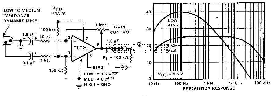
A microphone preamplifier utilizing a CMOS operational amplifier powered by its own battery is compact enough to fit within a small microphone casing. The amplifier functions with a 1.5V battery and exhibits low supply currents. This preamplifier operates at...

Today's electronic designs focus on optimizing efficiency to minimize unnecessary power dissipation, aiming to maximize battery life in portable applications and ensure that devices operate as cool as possible. One of the challenges facing designers of synchronous buck PWM...
This circuit is straightforward. The initial 555 timer prevents the second timer from being activated while the first is operational. Drive the circuit with a simple 12-volt power supply. The circuit utilizes two 555 timer integrated circuits (ICs) configured in...
The signal from a microphone is too weak for a standard line input. This low-noise DC-coupled microphone amplifier provides a solution for anyone who wants to connect a microphone to a high-fidelity installation. As shown in the schematic diagram,...
This microphone preamplifier utilizes the low-noise integrated circuit (IC) uA739. It serves as a practical example of designing an effective preamplifier for dynamic microphones. The IC contains two identical integrated preamplifier circuits, with the second preamp functioning in the...
Warning: include(partials/cookie-banner.php): Failed to open stream: Permission denied in /var/www/html/nextgr/view-circuit.php on line 713
Warning: include(): Failed opening 'partials/cookie-banner.php' for inclusion (include_path='.:/usr/share/php') in /var/www/html/nextgr/view-circuit.php on line 713