
adding audio to arduino projects
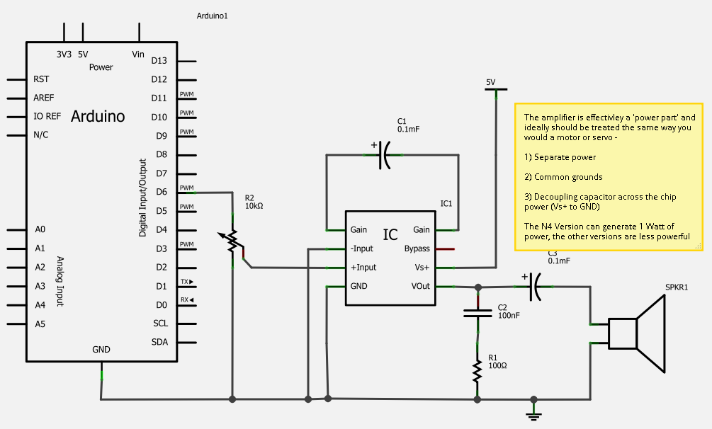
The LM386 amplifier circuit operates by amplifying low-level audio signals, making it an ideal choice for projects requiring sound output. The LM386-N4 variant is particularly popular due to its low cost and efficiency. The basic configuration includes connecting the audio input to the non-inverting input of the amplifier while the inverting input is grounded. A gain-setting resistor and capacitor are connected between the gain pin and ground, allowing for adjustable amplification levels. The output can be connected directly to speakers or through additional filtering components to enhance audio quality.
When designing circuits with the LM386, it is essential to consider the power supply. The LM386 can operate from a supply voltage of 4V to 12V, making it versatile for various applications. Bypass capacitors should be placed close to the power supply pins to reduce noise and improve performance.
In applications involving the Arduino Due, care must be taken due to the lower current handling capabilities of the ARM architecture. A series resistor, typically in the range of 1kΩ to 10kΩ, should be included to protect the DAC outputs from excessive current draw. This precaution helps prevent damage to the microcontroller while allowing for safe interfacing with the LM386 amplifier.
The integration of additional features such as pitch control and gating using LDRs enhances the functionality of the Auduino project. The use of LDRs allows for dynamic control over the audio output, simulating the decay of sound similar to stringed instruments. The Theremin-style note sensing introduces an innovative way to interact with sound, using hand movements to influence pitch and tone.
Overall, the LM386 amplifier and its integration with microcontrollers like the Arduino Due and Auduino represent a highly effective solution for generating quality audio in DIY electronics projects. The flexibility of the LM386 combined with creative modifications can lead to unique and engaging audio experiences.One incredibly simple solution to getting more sound from a micro controller is the LM386 series of amplifier chips. These can give project quality audio for less than a dollar. They even make a passable one dollar MP3 docking station and are the basis of the `little gem` guitar amplifier.
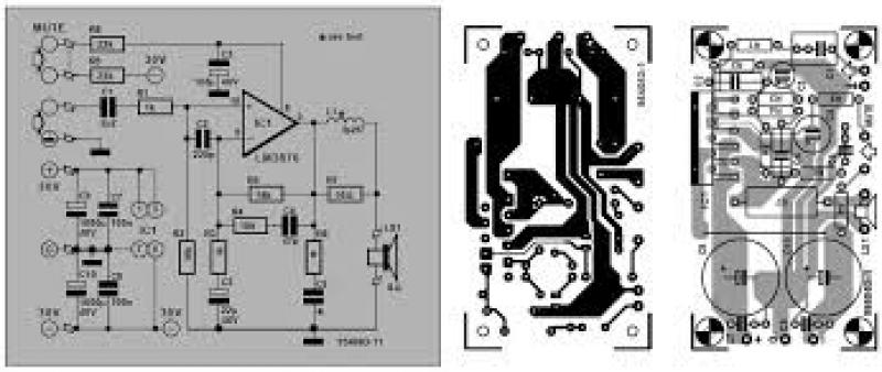
The datasheet for the LM386-N4 which I am using provides s ome example circuits but these require non standard capacitors - by non standard I really mean that most of us keep `decade` capacitors meaning the tens - 0. 01uf, 0. 1uf, 1uf, 10uf, 100uf. The sample circuits require 250uf and 0. 05 uf capacitors. As I didn`t have these values, I built the sample circuits with 100`s in series and 0. 1`s in parallel to get 200uf and 0. 05uf. After playing with the circuit for a while I removed the series and parallel capacitors leaving just a single 100uf and one 0.
01 uf capacitor. This variation of the recommended circuit works perfectly well, and is now included in the built version of the RCArduino Lap Timer. So for a super simple chip to add quality sound and volume to a project order a few LM386N4`s its amazing how many projects can benefit from bigger sound when its as easy as this.
Caution : The new generation of 32 Bit ARM chips used by the Arduino Due are less able to sink and source current than the AVR Chips used in the 8-bit Arduinos. A number of users have reported burnt out DAC (Digital To Analog Converter) outputs while using the Arduino Due.
It is suggested that a series current limiting resistor should be used between the Arduino Due DAC Outputs and external circuitry. There are currently a number of topics covering the Arduino DAC outputs and pin protection in general on the Arduino Due forum - Update: The first video is my own Auduino, any others I post are enhanced Auduino`s which for one reason of another are nicer than mine, so skip mine and have a look at what everyone else is able to get from this simple sketch through the use of clever additions - The project enclosure seems to be closely related to a pizza box but we can forgive that for the very musical session.
Modifications are obviously the stylus based pitch control and the addition of external echo. 1) An LED and LDR that `gates` the output, for those of us with no audio background, gating is essentially connecting and disconnecting a signal from the output. In DIY Projects LDRs are often used for this as they have an output which is a rough approximation to many stringed instrument where the initial note is loud but then decays away over time.
LDRs initially react to light very quickly, but when the light is removed, they settle more slowly allowing the not to linger slightly. 2) Thermin style note sensing. The user does not provide any details, but I assume that the note is being controlled by infra red bouncing off the users hand.
The original Audiuno design provided on tinkerkit uses five analogue inputs to control the sound, generally these are connected to puts but can also be replaced by any device capable of providing and analogue output. While I am a big fan of the Auduino, its not that well documented. It is described as a `granular synthesiser`, I spent a lot of time reading up on granular synthesis and reverse engineering the code before I was able to understand exactly how the Auduino generates its particular sound.
A granular synthesizer is usually described as generating sound by rapidly repeating a small `grain` of sound and if you read through the Auduino code you will certainly find repeated reference to grains however what and where are the grains Outside of the Auduino project, the term grain is most often used to describe grains of sound which are sampled from real life speech, instruments or environmental sounds - a grain is a very short sample in the order of 1/10 to 1/10, 000th of a second as opposed to the sampled vocal and drum tracks that you might be familiar with. The variables 🔗 External reference
Related Circuits
The air-cored inductor L1 is constructed using 13 turns of 1mm diameter enamelled copper wire, featuring an inner diameter of 10mm. The completed inductor is positioned over R7, with its terminals soldered to those of the resistor. All electrolytic...

This design can be used as a small booster. The amplifier is built around a balance stage. The quiescent current is set by diodes D1 and D2. The simplicity of the circuit, the quiescent current depends on the temperature...
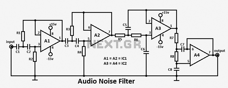
This audio noise filter circuit functions as a bandpass filter specifically designed for the audio frequency range. It effectively filters out unwanted signals that fall below or above the desired audio frequencies. The circuit comprises two filters: a low-pass...
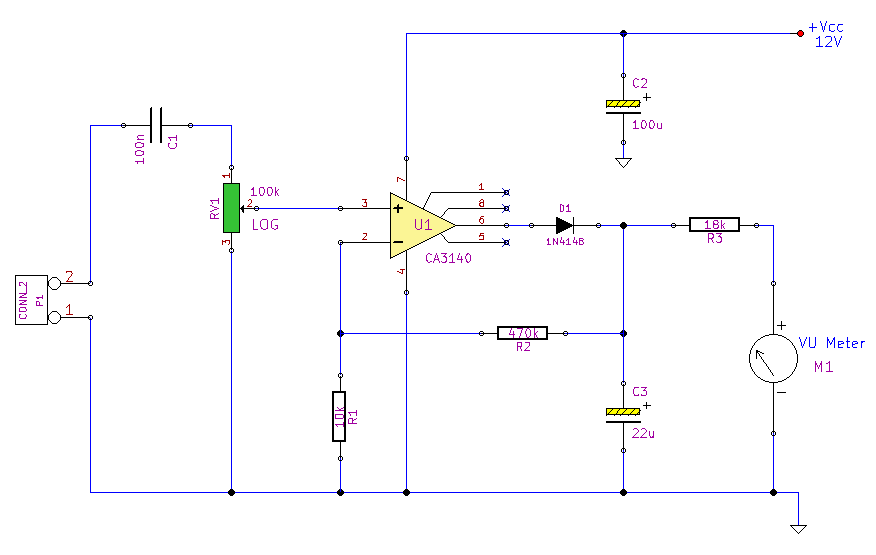
This simple circuit, designed with a minimal component count, indicates peak audio response on an analog meter, similar to a tape recorder's meter. It employs an operational amplifier configured as a non-inverting amplifier, with the addition of a diode...
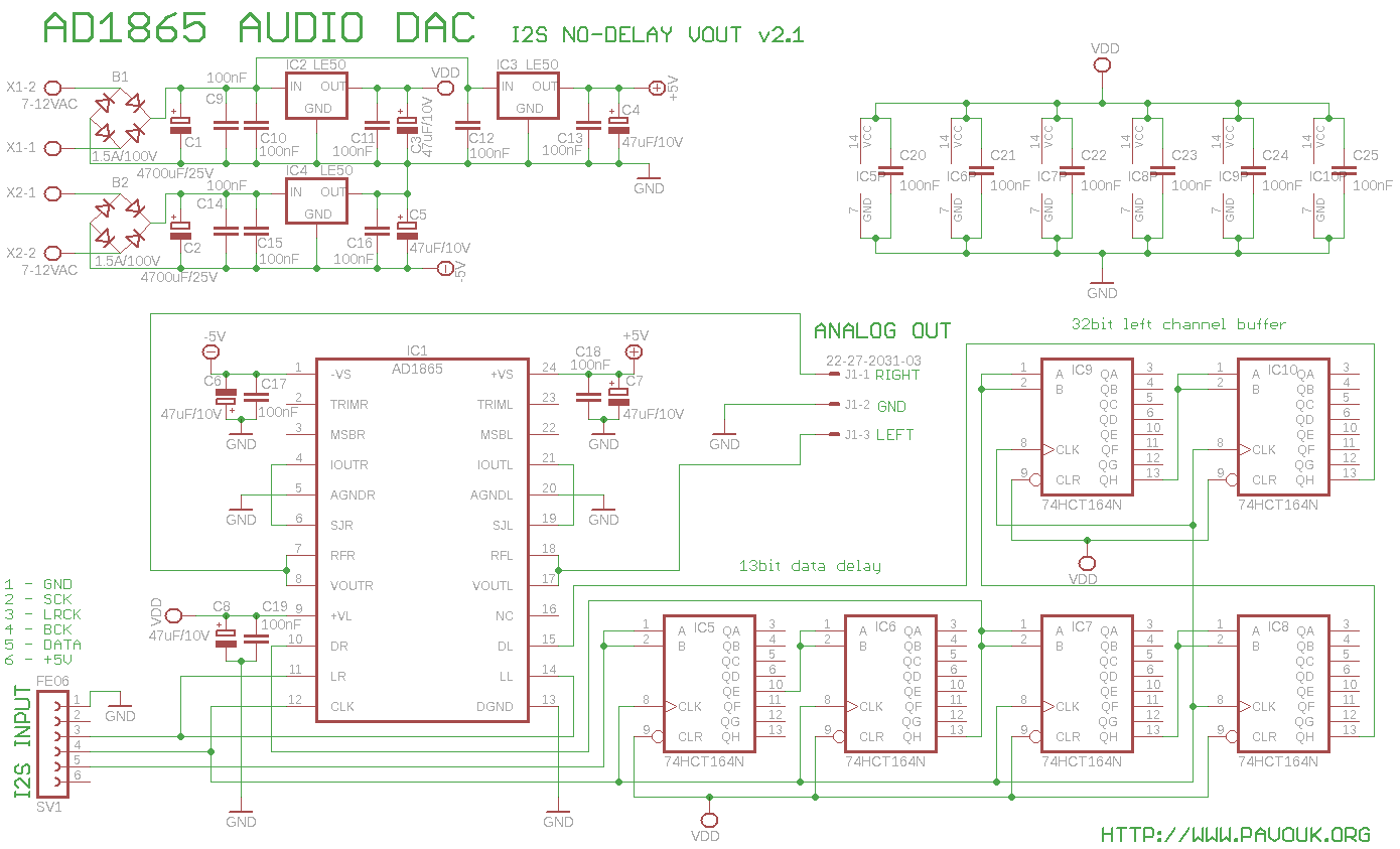
The AD1865 circuit is regarded as one of the best 18-bit stereo audio DACs available. Previous DAC designs encountered issues with weak current output, leading to the decision to utilize the integrated current-to-voltage (I/V) converter instead of an external...
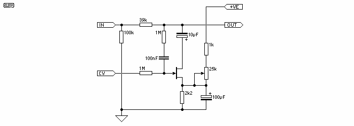
The circuit devised by Phil Allison still has some input voltage limitations, since it is based on a FET. Junction FET VCAs also create considerable distortion, with the worst of it appearing when the signal is attenuated by 6dB....