
LM3876 - High-Performance 56W Audio Power Amplifier with Mute
The air-cored inductor L1 plays a crucial role in the circuit, serving as a passive component that stores energy in a magnetic field when an electric current passes through it. The use of 1mm diameter enamelled copper wire ensures minimal resistive losses and enhances efficiency. The specified construction with 13 turns allows for a balance between inductance and physical size, making it suitable for the application at hand.
The integration of the inductor with resistor R7 is critical for maintaining circuit integrity and performance. Proper soldering of the inductor terminals to the resistor ensures reliable electrical connectivity, which is essential for the overall functionality of the amplifier circuit.
The requirement for electrolytic capacitors to be mounted upright is indicative of their construction, as improper orientation can lead to failure or reduced performance. This design consideration reflects best practices in circuit assembly.
The muting feature, controlled by a single-pole switch, offers flexibility in operation. By connecting the switch to the MUTE input (pin 8), the amplifier can be easily silenced when necessary. The option to solder a wire bridge across the mute terminals provides an alternative for applications where muting is not required, ensuring that the circuit remains adaptable.
The mention of R6-C6 indicates a design foresight for potential future applications, even if they are not required in the current configuration. This modularity allows for easy upgrades or modifications without significant redesign.
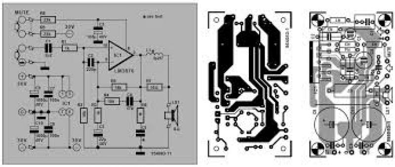
The optimization of the chips for an 8 Ohm load is a key specification, as it directly influences the performance characteristics of the amplifier. The noted decrease in output power when operating with a 4 Ohm load or reduced supply voltage highlights the importance of adhering to design specifications to avoid performance limitations. The activation of SPIKE protection at approximately 27V serves as a safety mechanism to prevent damage to the amplifier under adverse conditions, emphasizing the need for careful consideration of load impedance and supply voltage in practical applications.Air-cored inductor L1 consists of 13 turns of 1mm dia. enamelled copper wire with an inner diameter of 10mm. The completed inductor is pushed over R7 and its terminals soldered to those of the resistor. All electrolytic capacitors must be mounted upright. The amplifier can be muted with a single-pole switch connected to the MUTE input (pin8). This
function is enabled when the switch is open. If muting is not required, solder a wire bridge across the mute terminals on the board. The R6-C6 is not normally required in this application, but provision has been made for it for use in other applications. According to the manufacturers, both chips are optimalized for a load of 8 Ohm. The output power is lower when a 4 Ohm load is used or when the supply voltage is reduced. When a 4 Ohm load is used, the SPIKE protection becomes active when the supply voltage is about 27V, resulting a in a reduction of the power output to 10W.
This means that it is not advisable to use loudspeaker with an impedance <>
Related Circuits
The following diagram illustrates a 50W offline switching power supply circuit design. The circuit is powered by a MOSFET, specifically the BUZ80A/IXTP4N8 for a 220V AC voltage input and the GE IRF823 for a 110V AC input voltage. The...
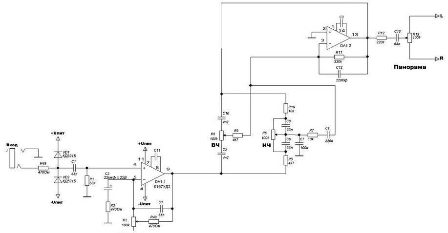
The four main input channels are identical and feature independently adjustable input sensitivity, tone, and sound panning. The fifth input is a linear channel. Despite its inexpensive and basic design, the Mini Audio Mixer "Impulse MM-04" performs satisfactorily. The Mini...
Switch on one unit, and everything else you need turns on automatically. This can save the tedium of turning on half a dozen different things, when one should be enough! This is another project created purely from necessity. In...
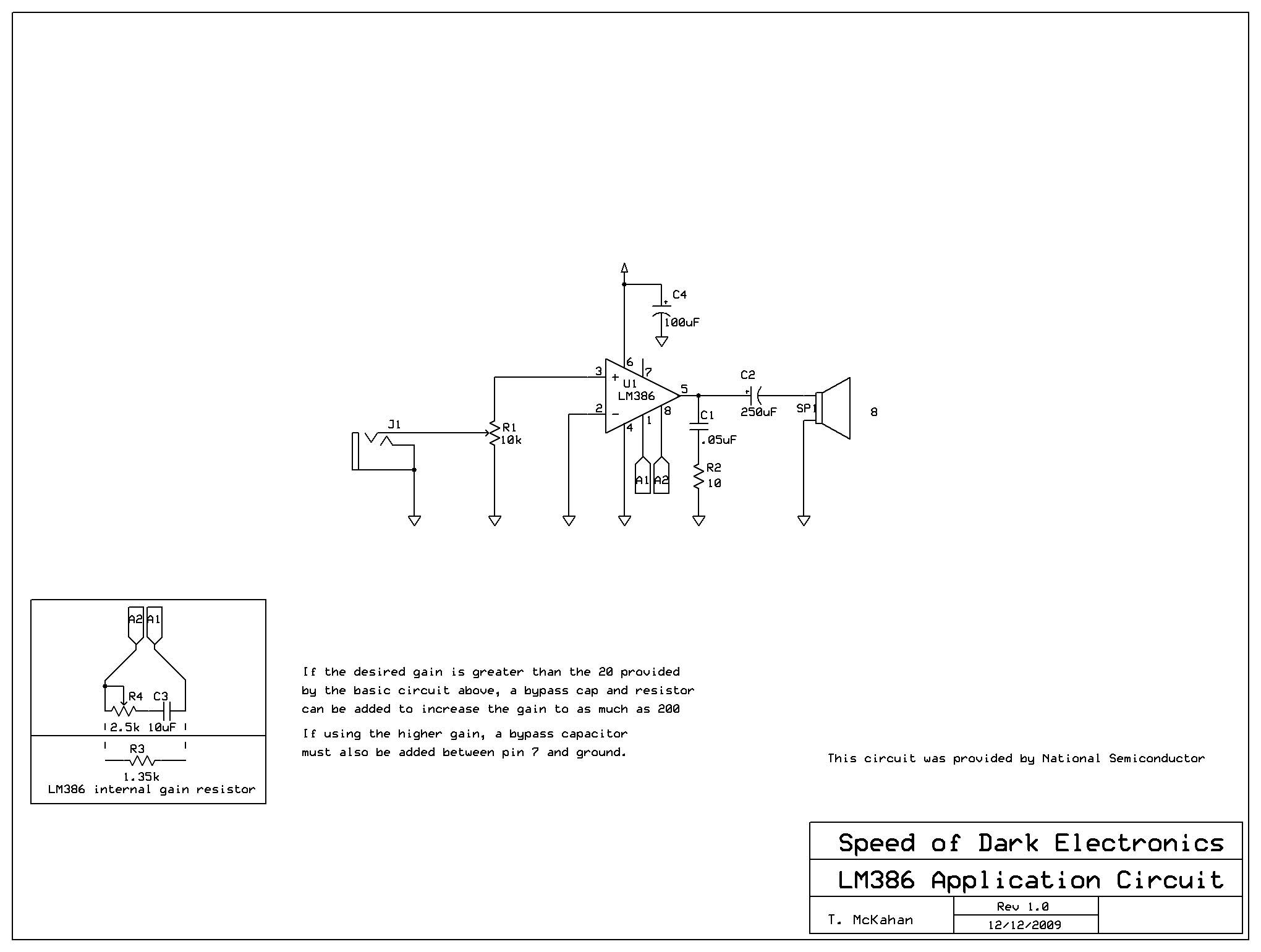
An LM386 Low Voltage Audio Amplifier was utilized for a project. The associated data sheet from National Semiconductor indicates that only five components are necessary for achieving a gain of 20, while seven components are required for a gain...

The CMOS 4001 consists of four independent two-input NOR gates. These gates are organized into two pairs. Gates 1 and 2 are connected to form a latching circuit. When the alarm is triggered, they will latch and activate the...
Powering this circuit with a 6V alkaline battery operates effectively with 100µF capacitors. However, there is an issue when attempting to replace the LED with a DPDT relay; a 6V relay previously available does not activate. Additionally, when using...