
lm 3915 sound level meter circuit
The sound level meter circuit primarily utilizes the LM3915, which is designed for audio level indication. This integrated circuit can drive either a bar graph or a dot display, providing versatility in visual representation of audio levels. The LM3915 operates with a supply voltage between 3V and 20V, making it suitable for various applications, from portable devices to fixed installations.
The circuit also includes a peak detector stage, which is essential for accurately capturing the peak audio levels. The BC558 transistor is employed in this stage to amplify the audio signal, while the 1N4001 diode is used for rectification, allowing the circuit to respond to the peak values of the incoming audio signals. This combination ensures that transient peaks in the audio waveform are effectively captured and displayed.
The input stage is designed for audio line levels, typically set at 1V peak to peak, with a maximum allowable input voltage of 1.3V. This specification is crucial for protecting the circuit from damage due to excessive input levels. The input can be connected directly to the output of an audio amplifier or to a microphone preamp, depending on the intended application.
For users who prefer the moving dot display, the configuration can be easily modified by disconnecting Pin 9 from the positive voltage supply. This adjustment alters the display mode, enhancing the visual feedback of the sound levels in real-time.
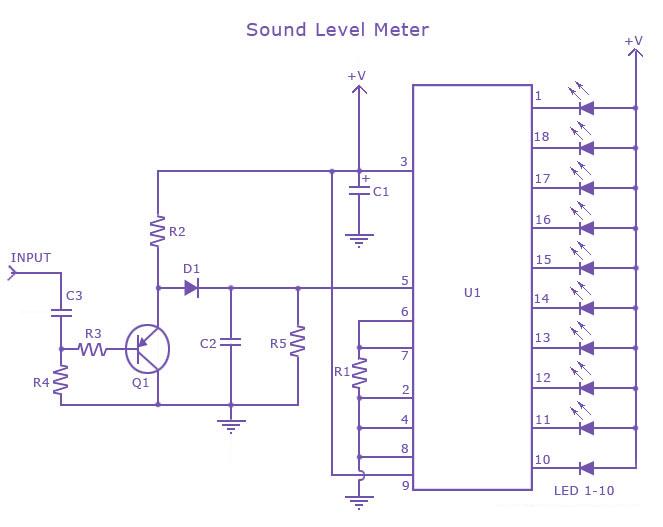
Overall, this sound level meter circuit offers a compact and effective solution for monitoring audio levels in various environments, making it a valuable tool for audio engineers, musicians, and hobbyists alike.This is a one chip sound level meter that can be use for displaying sound level of an amplifier or simply the sound level from a microphone. The heart of the circuit is IC LM 3915 Audio level IC. Even though it is a stand alone IC, a peak detector based on Transistor BC 558 and diode 1N4001 is also included for better performance.
Supply voltage ca n be from 3V to 20V. The input is set for audio line voltage (1V peak to peak) and has a max input voltage of 1. 3V. To make the circuit use a moving dot display instead of bar graph display, Pin 9 can be should be disconnected from +V. 🔗 External reference
Related Circuits
LED sequencer that follows the rhythm of music or speech, powered by a 9V battery, is a portable unit. The basic circuit illuminates up to ten LEDs in sequence, following the beat. The LED sequencer circuit operates by detecting audio...
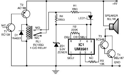
This heat detector alarm electronic project is designed using the UM3561 sound generator circuit and several common electronic components. The heat detector circuit employs a complementary pair of npn and pnp transistors to sense heat. When the temperature near...
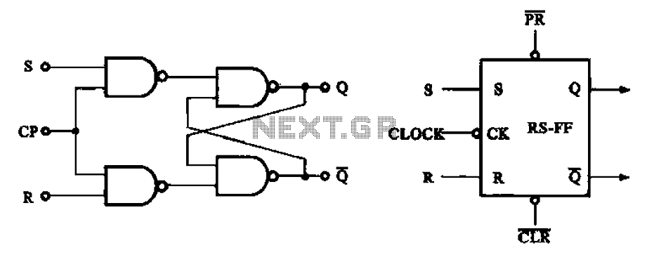
The asynchronous RS flip-flop mentioned earlier is not synchronized with the system clock signal. In contrast, the synchronous RS flip-flop incorporates synchronization, allowing it to operate in conjunction with the clock signal. Figure (a) illustrates the circuit configuration of...
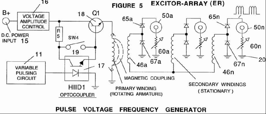
A power supply system utilizes a generator as a source of fuel to separate hydrogen and oxygen gases from natural water. It has the capability to control gas production by varying the amplitude of the voltage and/or the pulse...
This circuit is a wideband signal strength meter designed to respond to small variations in RF energy within the VHF spectrum. It is capable of detecting AM or FM modulation as well as a simple carrier wave. The circuit...
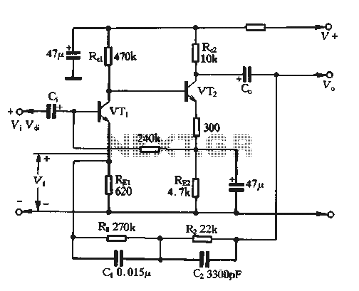
The feedback voltage (Vf) is derived from the output voltage (Vo) through an EQ network. The input voltage (Vf) is related to the subtraction process, yielding a pure input voltage for the circuit, which is associated with the tandem...