
Additional formula LP Recorder increased compensation circuit diagram image HQ

The circuit described focuses on enhancing the image quality of LP recorders by targeting specific frequency components of the television signal. The design includes a signal processing stage that filters and amplifies the 3 MHz frequency components, which are crucial for reproducing fine details and sharp edges in the displayed image.
To implement this circuit, a bandpass filter can be employed to isolate the 3 MHz frequency range. This filter can be designed using operational amplifiers (op-amps) configured in a Sallen-Key topology, which offers good selectivity and a manageable design complexity. Following the filter stage, an adjustable gain stage can be incorporated using a variable resistor (1 kΩ) to allow for fine-tuning of the signal strength, optimizing the brightness and clarity of the output image.
The feedback mechanism in the circuit ensures that variations in incoming signal strength do not adversely affect the picture quality. A second variable resistor (10 kΩ) can be connected to a potentiometer to provide additional control over the output level, allowing for user adjustments based on the specific content being viewed. This feature is particularly important as different video signals can exhibit varying characteristics, necessitating tailored adjustments to achieve optimal clarity.
The overall circuit design must consider power supply requirements, ensuring that all components are adequately powered for reliable operation. Additionally, care should be taken to minimize noise and interference, which could degrade the enhanced image quality. Shielding and proper grounding techniques should be implemented to maintain signal integrity throughout the processing stages.
In conclusion, this circuit provides a sophisticated solution for enhancing the image quality of LP recorders by focusing on critical frequency components, allowing for user adjustments to achieve the best possible viewing experience.After this circuit can compensate for additional LP recorder function defects in image quality. Television signal frequency component reflects details of the screen, as will be appropriate to enhance the high frequency component can be increased edge sharpness of the screen, called detail enhancement, which is used in modern video recorder technology of four HQ one. This circuit television signal 3MHz nearby components to enhance, to improve picture clarity and sense of contour.
Practice has proved that the picture quality of LP state had a better. When adjusting, open the VCR, adjust the variable resistor 1k Europe until the brightest picture. Due to compensate for the different signals are not the same, to be adjusted according to the picture potentiometer 10k European situation when in use, so the clearest picture.
Related Circuits
A series of shunts and multipliers selected by a switch can be utilized in conjunction with a single basic meter to create a multirange instrument, commonly referred to as a multimeter. This device is capable of measuring voltage, current,...
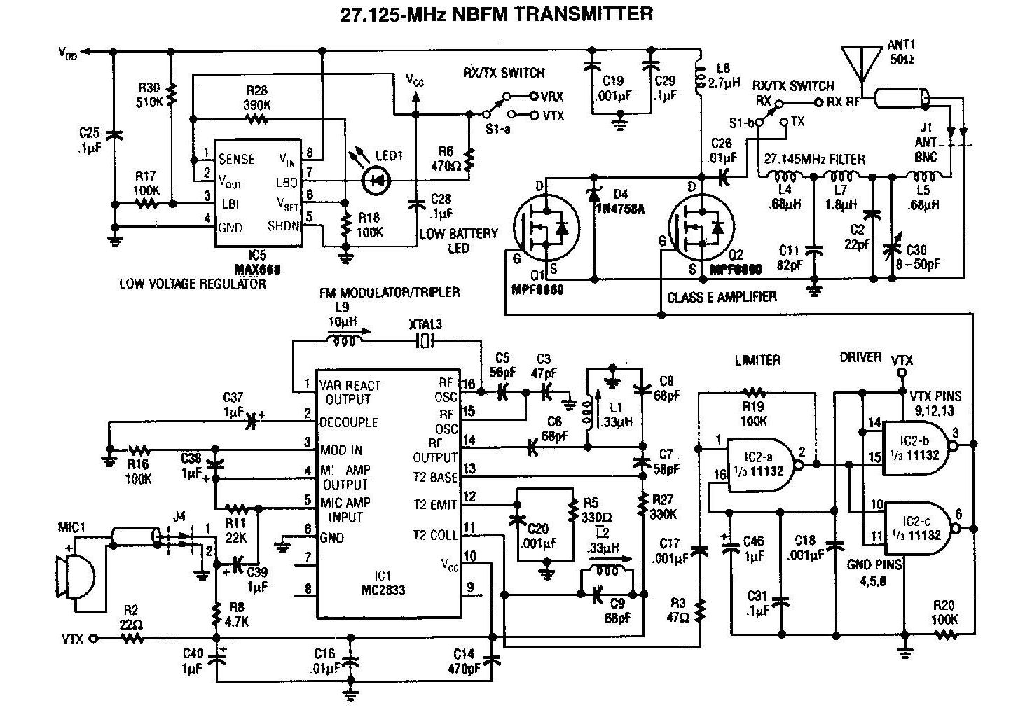
A 27MHz transmitter circuit schematic utilizing the MC2833 and two FET transistors, MPF6660. This design incorporates a Motorola MC2833 one-chip FM transmitter along with several supporting components. The 27MHz transmitter circuit is designed to operate within the FM radio frequency...
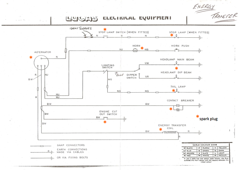
Timed precisely with the pistons' pumping, this component works with the ignition coil to create the voltage jump that causes the spark in the spark plug. The engine cut-out switch serves as an emergency button; when pressed, it provides...
Designed for communications use, this equalizer circuit utilizes a Mitsubishi M5226P audio equalizer IC to modify frequency response. It operates with a supply voltage ranging from 9 to 20 V. Capacitors C6 through C16 are polyester film capacitors with...
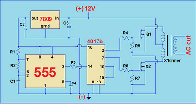
This project involves a simple 12V to 220V modified sine-wave inverter utilizing a 555 timer IC and a CD4017 decade counter. The inverter is capable of delivering 300W of continuous power and approximately 500W of maximum power output for...
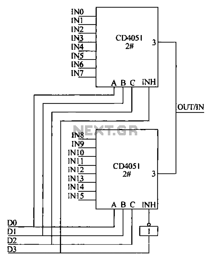
The CD4051 is a single-ended input 8-channel multiplexer that features three channel select inputs (A, B, C) and an inhibit input (INH). The signals at inputs A, B, and C are utilized to control the selection of one of...