
NBFM 27MHz Transmitter Circuit
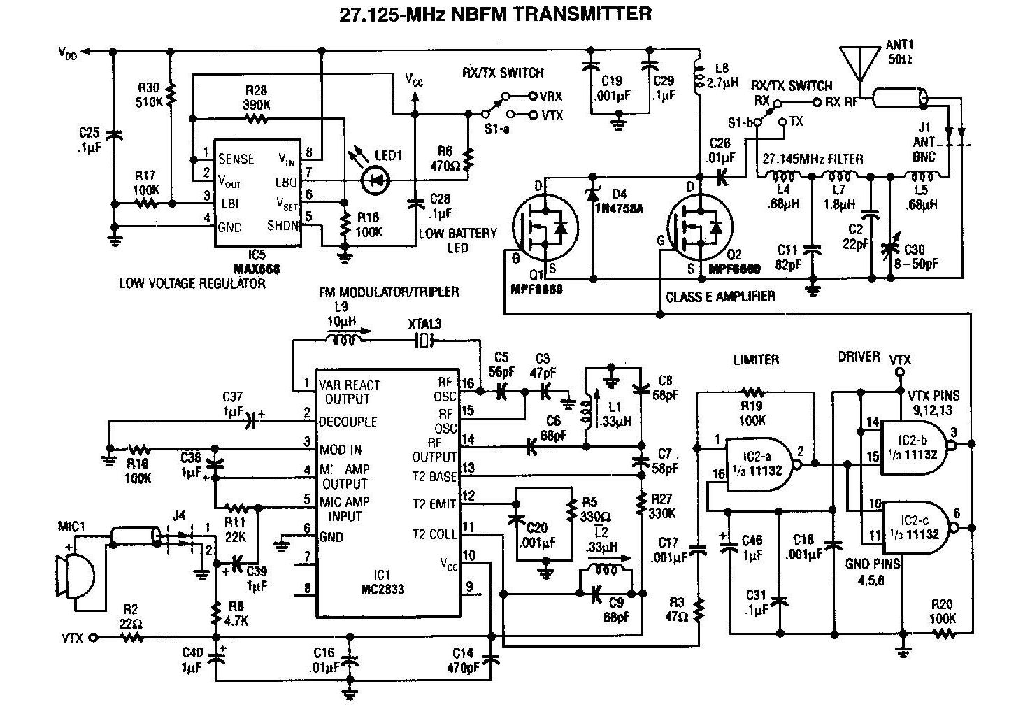
The 27MHz transmitter circuit is designed to operate within the FM radio frequency range, specifically at 27 MHz, which is often used for various short-range communication applications. The core of this circuit is the Motorola MC2833, a highly integrated FM transmitter chip that simplifies the design process by incorporating essential functions such as modulation, oscillator, and output amplification in a single package.
The MC2833 requires minimal external components for operation, primarily consisting of passive elements like resistors, capacitors, and inductors that help set the frequency and stabilize the circuit. In this schematic, the two MPF6660 FET transistors serve as amplifiers, enhancing the output signal from the MC2833 to ensure sufficient power for transmission. The use of FET transistors is advantageous due to their high input impedance and low noise characteristics, which contribute to improved signal quality and efficiency.
The circuit typically includes a power supply section that provides the necessary voltage levels for the MC2833 and the FETs, ensuring reliable operation. Additionally, an antenna matching network may be included to optimize the transmission efficiency by matching the output impedance of the transmitter to the antenna.
Overall, this 27MHz transmitter circuit schematic offers a compact and effective solution for FM transmission, suitable for applications such as wireless audio transmission, remote control systems, and other short-range communication devices. Proper layout and component selection are crucial to minimize interference and maximize performance, ensuring that the transmitter operates within the desired frequency band while maintaining signal integrity.A 27MHz transmitter circuit schematic with MC2833 and 2 FET transistors MPF6660. Using a Motorola MC2833 one-chip FM transmitter, a few support components.. 🔗 External reference
Related Circuits
This solid-state Tesla Coil design is similar to the two-transistor version available on this site, utilizing a standard flyback transformer to generate high voltage output. Unlike the previous design, it employs a 555 timer to effectively drive a single...
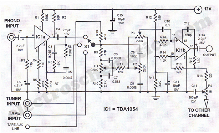
This Hi-Fi stereo preamplifier circuit is designed using the TDA1054 integrated circuit from SGS. The TDA1054 is a 16-pin DIL package that incorporates two separate preamplifier circuits. It is a low-noise preamplifier with minimal complications in the design process....
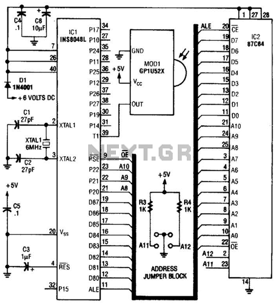
This circuit is based on the Sharp GP1U52X infrared module and the 1NS8048L microprocessor. The GP1U52X is a hybrid integrated circuit and infrared detector that provides a strong, clean signal for subsequent filtering and demodulation. The circuit utilizes the Sharp...
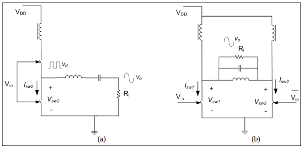
The measured output power and efficiency of a 6 dBm 130nm CMOS class-D inverter chain was analyzed, utilizing gate bias variation to generate a pulse width modulated inverter output voltage (Cijvat et al., 2008). Efficiency versus output power was...
PC parallel port can be very useful I/O channel for connecting your own circuits to PC. The PC's parallel port can be used to perform some very amusing hardware interfacing experiments. The port is very easy to use when...
GND and VCC are positioned perpendicularly to the other pins in the circuit diagrams, while the actual Z80 is a DIP with no pins in these locations. This arrangement complicates the readability of the circuit diagram, necessitating a mapping...