
12V-220V Modified Sine-wave Inverter Circuit

Part List (60Hz, 220V):
- R1 – 20 kilo-ohms, 1/4W
- R2 – 20 kilo-ohms, 1/4W
- R3 – 1.2 kilo-ohms, 1/4W
- R4, R6 – 560 ohms, 1/4W
- R5, R7 – 5.6 kilo-ohms, 1/4W
- C1 – 100nF capacitor
- C2 – 10uF electrolytic capacitor, rated 16V
- C3 – 470uF electrolytic capacitor, rated 16V
- C4 – 100nF capacitor
- Q1, Q2 – IRFZ44N or similar N-channel power MOSFET
- Transformer – 10V-0V-10V to 220V transformer (minimum 500VA if required)
- LM7809 – IC voltage regulator
- LM555 – timer IC
- CD4017b – 5-stage Johnson counter
- 12V – 12V lead-acid battery
The inverter circuit operates by using the 555 timer in astable mode, which generates a square wave output. This square wave is then processed by the CD4017 decade counter, which divides the frequency to produce a modified sine wave output. The output from the CD4017 is used to drive the gates of the N-channel MOSFETs (Q1 and Q2), which act as switches to control the power delivered to the transformer. The transformer steps up the voltage from 12V to 220V, enabling the inverter to supply power to standard AC loads.
The choice of components is crucial for ensuring the inverter's performance. The resistors and capacitors in the timing circuit determine the frequency of the output waveform, while the MOSFETs must be selected based on their voltage and current ratings to handle the load effectively. The use of an appropriate transformer is also essential to ensure that the inverter can supply sufficient power without overheating or saturating.
In summary, this inverter design is a practical solution for converting low-voltage DC power into high-voltage AC power, suitable for various applications, particularly as a backup power source. Proper attention to component selection and circuit design ensures reliable operation and efficiency.This project is a simple 12V to 220V modified sine-wave inverter using 555 timer IC and CD4017 decade counter. This inverter can deliver 300W continuous power and around 500W max power output (short period). A very good inverter for uninterruptible power supply (UPS). The driver of the inverter is the 555 timer and 4017 decade counter. 555 timer generate pulses at a frequency of four times the desired output frequency. For example, if you want a 60Hz output, the timer frequency must be equal to 240Hz (4*60Hz). For 50Hz output, 200Hz is the output of 555. You can try different combination of R1, R2, and C1 to obtain the desired frequency by using the 555 calculator. The use of LM7809 regulator is to protect the 555 and 4017 from voltage spikes and transients that can influence their operation and stability.
You can use LM7808, LM7806, or 7805 regulator or any regulator IC available at hand. But take note that the regulator output must be 5V and above to make sure that you can drive the Mosfet Q1, and Q2. The diagram below is the comparison of modified and pure sine wave. Both have the same peak value and RMS value. Part List (60Hz, 220V): R1 – 20 kilo-ohms 1/4W R2 – 20 kilo-ohms 1/4W R3 – 1.2 kilo-ohms 1/4W R4, R6 – 560 ohms 1/4W R5, R7 – 5.6 kilo-ohms 1/4W C1 – 100nF capacitor C2 – 10uF electrolytic capacitor rated 16V C3 – 470uF electrolytic capacitor rated 16V C4 – 100nF capacitor Q1, Q2 – IRFZ44N or similar N-channel power Mosfet X’former – 10V-0V-10V to 220V transformer (minimum 500VA if required) LM7809 – IC regulator LM555 – timer IC CD4017b – 5-stage Johnson counter 12V – 12V lead acid battery
🔗 External reference
Related Circuits
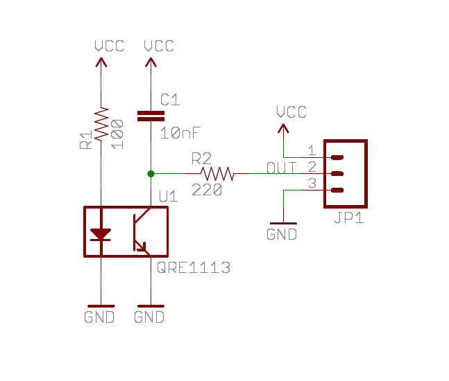
A real-time clock turns off the counter at night to conserve power. When a bee crosses under the LED, the light is reflected back to the sensor, which is a phototransistor, and triggers a digital input to the Arduino...
The circuit element appears to be problematic, particularly with the Shu component. After a prolonged period following the activation of the start button, there are indications of unexpected behavior, such as the turtles producing sperm-like substances. The Pi Wen...
This radio receiver can operate with any of the following transistors: ZN414, MK484, or TA7642. The radio receiver circuit is designed to utilize a variety of transistors, specifically the ZN414, MK484, and TA7642, which are commonly used in low-power AM...
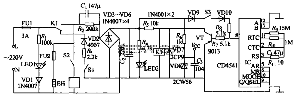
The industrial fuel oil furnace controller circuit consists of a power supply circuit, a testing and ignition control circuit, and a control implementation circuit, as illustrated in the accompanying diagram. The power supply circuit includes a step-down capacitor (C6),...
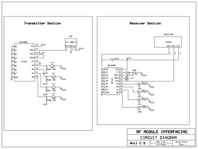
This document presents a circuit example for interfacing an RF module using the HT12E/D encoder-decoder pair. The attached circuit can be utilized for data transmission via the RF module, which is designed for single-channel operation, allowing only serial data...
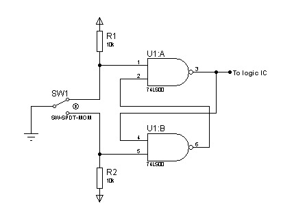
In most digital electronics projects that utilize various types of switches, switch bounces are frequently encountered. These are additional glitches that occur following the actual operation of the switch. These small pulses can disrupt the proper functioning of the...