
Adjustable Constant Current Regulator

The adjustable constant current regulator circuit is designed to provide a stable output current regardless of variations in load resistance or input voltage. This feature is particularly useful in applications such as bench power supplies where sensitive electronic components need to be tested without the risk of overcurrent conditions that could lead to damage.
The circuit typically consists of a voltage reference, an operational amplifier, and a pass transistor. The voltage reference sets the desired output current level, while the operational amplifier compares the output current with the reference voltage. The pass transistor is used to regulate the current flowing to the load based on the feedback from the operational amplifier.
To implement this circuit, the following components are essential:
1. **Voltage Reference**: A precision voltage reference IC (e.g., LM4040) can be used to provide a stable reference voltage. This voltage is used to set the desired output current.
2. **Operational Amplifier**: An op-amp (e.g., LM358) is used to compare the output current, which can be measured using a shunt resistor, against the reference voltage. The op-amp will adjust the base drive of the pass transistor to maintain the output current at the set level.
3. **Pass Transistor**: A power transistor (e.g., TIP31) acts as the current regulator. It adjusts its conduction based on the feedback from the op-amp to maintain the current at the desired level.
4. **Shunt Resistor**: A low-value resistor is placed in series with the load to measure the output current. The voltage drop across this resistor is fed back to the operational amplifier for comparison with the reference voltage.
The output current can be adjusted by varying the reference voltage, which can be done using a potentiometer connected to the voltage reference. This allows for flexibility in testing different loads without the risk of exceeding safe current levels.
In summary, the adjustable constant current regulator circuit is a vital tool in electronic testing and development, ensuring that circuits under test receive a controlled and safe amount of current. Proper design and implementation of this circuit can significantly enhance the reliability and safety of electronic testing procedures.This is Adjustable Constant Current Regulator circuit. This circuit can be used in a bench power supply to prevent the circuit that are tested from being. 🔗 External reference
Related Circuits

This circuit allows for the establishment of a maximum output current limit from a power supply unit (PSU). It is particularly beneficial when initially powering a project or conducting a soak test. By imposing an upper current limit, protection...
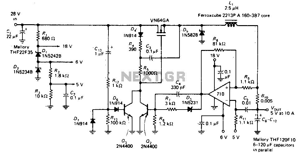
This circuit provides a regulated DC output with less than 100 mV of ripple for microprocessor applications. The required operating voltages are derived from a bleeder resistor network connected across the unregulated 28 V supply. The output of the...
Switching Regulator for High Power Efficiency. When it is necessary to convert a high voltage to a significantly lower voltage, a switching regulator is the optimal choice. A switching regulator is an essential component in modern power management systems, particularly...
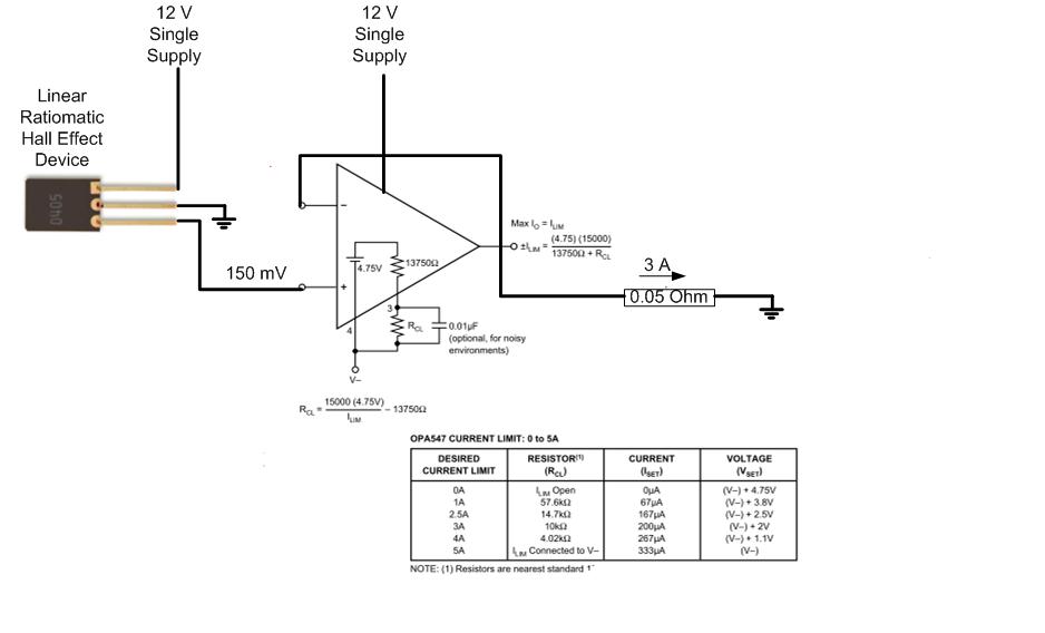
The proposed approach would dissipate (12V)(3A) = 36 watts, which results in significant heat generation in the circuit. This necessitates consideration of two alternatives: 1) Operating the op-amp at a lower supply voltage, if feasible, or 2) Utilizing a...
This device is designed to serve as a simple and cost-effective comparator, intended for use in a solar cell power supply system where a quick indication of either too low or acceptable voltage is required. The circuit includes one...
This circuit allows for the adjustment of fan speed from a distance, such as from a couch or bed. It utilizes the TSOP1738 infrared receiver module to capture the infrared signals. The circuit operates by employing an infrared remote control,...