
Solar Cell Voltage Regulator
This comparator circuit is particularly beneficial in applications involving solar power systems, where monitoring voltage levels is crucial for maintaining efficient operation. The use of a low-drop voltage regulator, such as the 4805, ensures that the circuit can operate effectively even with lower input voltages, which is common in solar applications due to varying sunlight conditions. The choice of complementary transistors allows for a responsive and reliable switching mechanism, capable of toggling the LEDs based on the voltage thresholds set by the resistors in the voltage divider networks.
The circuit's design is modular, allowing for adjustments to be made based on the specific characteristics of the solar cells used and the load requirements. The voltage divider resistors can be selected or modified to tailor the activation points of the LEDs to the desired voltage levels, ensuring that the indicators provide accurate feedback on the system's performance. The addition of a buzzer enhances the functionality of the circuit, providing an auditory alert that complements the visual indicators, thus improving the overall user experience.
In summary, this simple comparator circuit is an effective solution for monitoring solar cell power supplies, providing clear visual and auditory indications of voltage levels to prevent under-voltage conditions and ensure reliable operation of connected devices. The design's flexibility and low power consumption make it suitable for various applications in renewable energy systems.This device is designed to be a simple, inexpensive comparator`, intended for use in a solar cell power supply setup where a quick too low` or just right` voltage indicator is needed. The circuit consists only of one 5V regulator, two transistors, two LEDs, five resistors, two capacitors, and one small battery.
Although a 4-V battery is indicated, 4. 5 V (3 alkalines in series) or 3. 6 V (3 NiCd cells in series) will also work. The specifications of voltage regulator IC1 are mainly determined by the size and number of the solar cells and the current pull of the equipment connected to the output. Here the low-drop 4805 is suggested but other regulators may work equally well as long as you observe the output voltage of the solar cells.
Transistors T1 and T2 are complementary types i. e. one each of the pnp and npn variety. Although the ubiquitous BC557B (pnp) and BC547B (npn) are indicated, any small-signal equivalents out of the junk box will probably do. The values of voltage dividers R1/R6 and R3/R4 may need to be adjusted according to the type of transistor and its gain, or according to the desired voltage thresholds.
Using the resistor values shown in the schematic, LED D2 turns on fully when the voltage is just above 5 volts. LED D1 turns on when the voltage drops below 4. 2 volts or so. Between those two thresholds, there is a sort of no man`s land where both LEDs are on dimly. A buzzer or other warning device could be connected across the terminals of LED D1 to give a more substantial warning if the voltage drops below operating limits.
The current consumption of the circuit is about 20 mA at 5 V, and it decreases with the voltage supplied by the solar cells. 🔗 External reference
Related Circuits
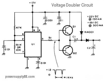
This circuit diagram represents a DC voltage doubler and DC converter. It is designed to convert a 12V DC power supply into outputs of 24V DC and 18V DC. Nearly any PNP or NPN power transistors can be utilized...
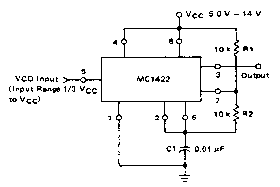
The VCO circuit, which has a nonlinear transfer characteristic, will operate satisfactorily up to 200 kHz. The VCO input range is effective from V% Vcc to Vcc - 2 V, with the highest control voltage producing the lowest output...
A small Tesla Coil (12-inch range), Jacob's Ladder, or an "Antigravity Project" from the book "Electronic Gadgets for the Evil Genius" is being discussed, but sourcing parts for these projects has proven challenging. The book is informative, yet the...
The LED is a fascinating component for amateur electronics hobbyists. The primary characteristic of an LED is that it requires a minimum of 3 volts to illuminate. Various circuits have been discovered to drive an LED using a single...
This site serves as a collection of useful information that the author wishes to retain, with the occasional inclusion of pages that may be of interest to others. The author has documented the retrofit of the Boxford 125 TCL...
The Traynor YBA-1 is closely related to the classic Bassman/JTM-45 circuit. A vintage '67 model was acquired, which was in excellent condition except for a poorly executed reversible master volume modification and a burnt power transformer. This version features...