
Adjustable oscillator
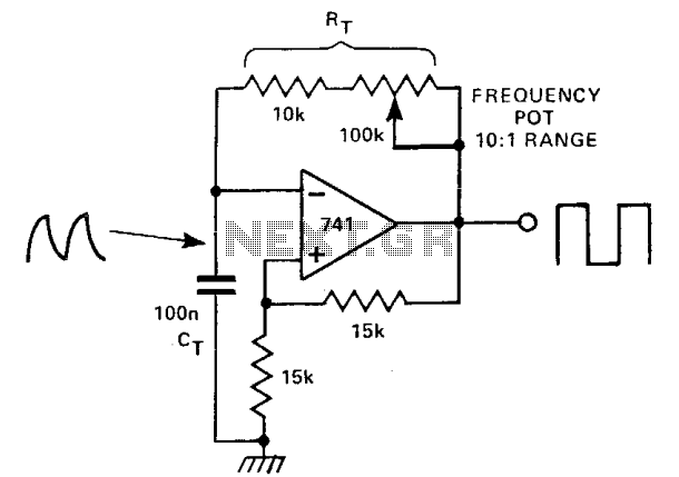
At this point, the output voltage is -10 V, and the voltage at the inverting terminal continues to decrease according to the same time constant. By adjusting this time constant using a variable resistor, it is possible to generate a variable frequency oscillation.
The circuit utilizes an operational amplifier configured with two feedback paths that enable distinct operational characteristics. The positive DC feedback path is crucial for establishing hysteresis, which is a defining feature of Schmitt triggers. This hysteresis allows the circuit to provide clean transitions between high and low states, effectively filtering out noise and ensuring stable operation.
The CR timing network plays a pivotal role in controlling the rate at which the voltage at the inverting terminal rises. The time constant, denoted as CTRT, is determined by the values of the resistor and capacitor in this network. As the voltage at the inverting terminal increases, it approaches the threshold of +5 V. When this threshold is crossed, the op-amp's output switches from a high state to a low state, resulting in an output of -10 V.
The subsequent behavior of the circuit is influenced by the CR timing network's time constant. As the output voltage drops to -10 V, the voltage at the inverting terminal begins to decrease. The rate of this decrease is governed by the same time constant, allowing for a predictable oscillation pattern. By incorporating a variable resistor in the timing network, adjustments can be made to the time constant, thereby enabling the generation of variable frequency oscillations. This feature is particularly useful in applications requiring signal modulation or waveform generation, showcasing the versatility of this op-amp-based circuit design.In this circuit, there are two feedback paths around an op-amp. One is positive dc feedback which forms a Schmitt trigger. The other is a CR timing network. Imagine that the output voltage is +10 V. The voltage at the noninverting terminal is +15 V. The voltage at the inverting terminal is a rising voltage with a time constant of CTRT. When this voltage exceeds + 5 V, the op amp's output will go low and the Schmitt trigger action will make it snap into its negative state. Now the output is -10 V and the voltage at the inverting terminal falls with the time constant as before. By changing this time constant with a variable resistor, a variable frequency oscillation may be produced.
🔗 External reference
Related Circuits
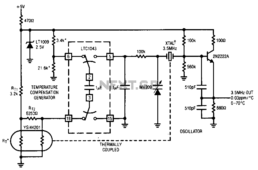
This circuit employs the LTC1043 to distinguish between a temperature sensing network and a de reference. The single-ended output biases a varactor-tuned crystal oscillator to compensate for drift. The varactor crystal network exhibits high de impedance, negating the necessity...
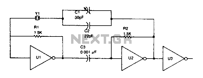
TTL inverter stages, U1 and U2, are cross-connected with a crystal Y1. A resistor in each stage biases the normally digital gates into a region where they operate as amplifiers. Inverter stage U3 is used as a buffer. The circuit...
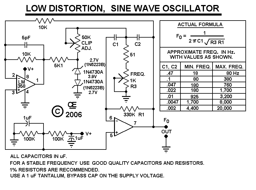
After constructing the device, adjust the frequency to the desired level using the "Frequency Control." Then, utilize an oscilloscope to fine-tune the waveform for optimal performance with the "Clip Control." The sharp rise and fall times of square waves...
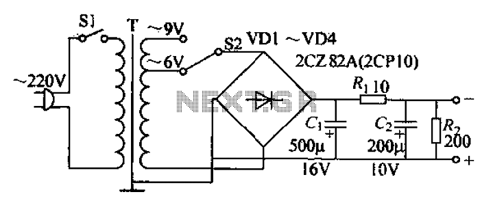
The adjustable current power supply circuit operates at 6V and 9V, utilizing a minimal number of components, which facilitates easy assembly. The circuit can deliver an adjustable output current of up to 100mA, serving as a suitable alternative to...
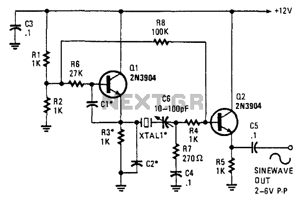
This oscillator employs two transistors and operates the crystal in its fundamental mode. Capacitors CT and C2 should be approximately 2,700 pF for 1 MHz, 680 pF for 5 MHz, and 330 pF for 10 MHz. A capacitance of...
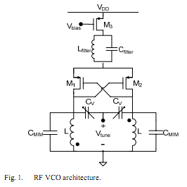
The oscillator is designed to tune from 1.8 GHz to 2 GHz for typical cellular telephony applications. An extended tuning range can be obtained by adjusting the ratio between the varactor capacitance and fixed capacitance in the tank. PMOSFETs...