
Logic Gates FM Transmitter Circuit

The FM transmitter circuit utilizing logic gates is a fundamental electronic design that operates by modulating a carrier frequency with an audio signal. This circuit typically consists of various logic gates such as AND, OR, and NOT gates, which are used to process the input audio signal and generate the modulated output.
In a typical design, the circuit begins with an audio input stage where the sound signal is fed into the logic gates. The gates are configured to manipulate the signal according to the desired modulation scheme. For instance, an AND gate may be used to combine the audio signal with a high-frequency carrier wave generated by an oscillator circuit. The output from the AND gate then represents the modulated signal.
Next, the circuit may include a low-pass filter to eliminate any high-frequency noise and ensure that only the desired frequency range is transmitted. Following this stage, a power amplifier can be incorporated to boost the signal strength before transmission. The final output is then fed into an antenna, allowing the FM signal to be broadcast over a designated frequency range.
Additionally, it is essential to consider the power supply requirements for the circuit, ensuring that all components receive the appropriate voltage and current levels for optimal performance. Proper grounding and shielding techniques should also be implemented to minimize interference and enhance signal clarity.
In summary, the logic gates FM transmitter circuit is a versatile and efficient design that leverages digital logic components to achieve analog signal modulation, making it suitable for various applications in audio transmission and wireless communication.Logic Gates FM Transmitter Circuit Electronic Circuit Schematic Wiring Diagram. 🔗 External reference
Related Circuits
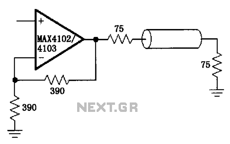
The MAX4102/4103 serves as a video configuration and RF distribution amplifier. The signal input for the MAX4102/4103 undergoes amplification before being output. To minimize the reflection during the transfer process, it is essential to select a termination impedance that...

The purpose of this circuit is to maintain a permanent magnet DC motor at a constant speed, which is set externally. This is achieved by monitoring the current flowing through and the voltage across the motor's brushes. The schematic for...
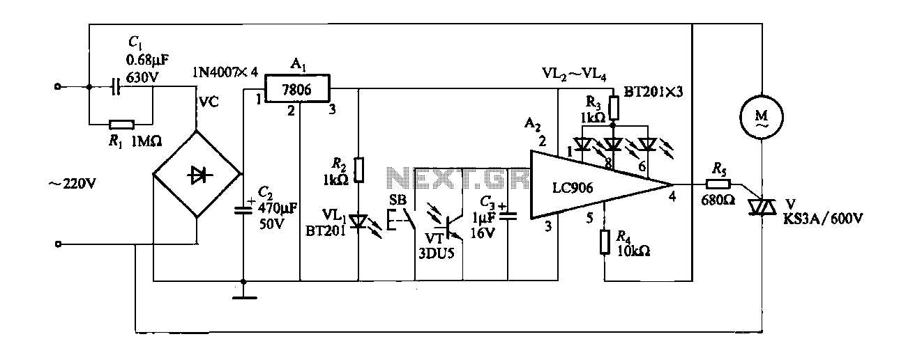
The ceiling fan speed control circuit depicted in Figure 3-6 utilizes a capacitor step-down method and a three-terminal fixed 7806 voltage regulator. It achieves fan speed control through the integrated circuit A2, which regulates the conduction angle of the...
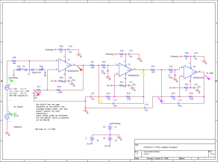
A bandwidth-limited amplifier shapes the waveform sampled by the 40 MHz high-speed pipeline Analog to Digital Converter (fast ADC, or fADC). It is well known that the shaping time is twice the time constant (peaking time) for each pole...

A simple battery charger designed for Nickel Metal Hydride batteries that require current-regulated charging. The charger delivers a charging current of 140 mA for efficient battery charging. The power supply section includes a 0-18 volt AC 1 Ampere step-down...
The IR Jammer is a fun project that provides a bit of safe, non-destructive fun. The Infrared Remote Control Jammer allows you to render all IR remote controls inoperative! The microcontroller in this design allows for all 6 of...