
Schematic Diagram Schema HO Train Model Lighthouse Flasher

The circuit described employs a typical oscillator configuration that generates two distinct waveforms: a triangle waveform and a square waveform. The triangle waveform is essential for controlling the brightness of an LED through a voltage regulator circuit. The voltage regulator ensures that the LED receives a stable current, which is critical for achieving consistent brightness levels. The triangle waveform, characterized by its linear rise and fall, allows for a gradual increase in LED brightness, creating a smooth lighting effect.
The square waveform plays a crucial role in generating the strobe effect. After passing through a capacitor, the square wave is directed to a power FET (Field Effect Transistor). The FET is utilized for its high current handling capabilities, allowing it to drive the LED with significant power. The timing of the square wave is designed to produce rapid on-off cycles, resulting in a high current pulse that causes the LED to flash brightly.
The strobe effect is achieved by carefully timing the transitions between the LED's bright and dim states. Initially, the LED gradually brightens as the triangle waveform increases, creating a soft glow. Once it reaches a peak brightness, the square waveform takes over, rapidly pulsing the LED to an even brighter state before allowing it to dim again. This sequence simulates the appearance of a rotating alarm light, which is often used in emergency signaling applications.
Overall, this oscillator circuit effectively combines both waveforms to create a visually striking lighting effect suitable for various applications, including decorative lighting, signaling devices, and alarm systems. The design emphasizes the importance of waveform characteristics in achieving specific visual outcomes, demonstrating the versatility of oscillator circuits in electronic design.The aboriginal accessory forms a archetypal oscillator ambit whose achievement is both a triangle waveform arresting and a aboveboard beachcomber signal. The triangle arresting is baffled to a accepted regulator circuit, which converts the triangle voltage arresting to a triangle accepted arresting through the alarm LED.
The aboveboard beachcomber arresting is aboriginal beatific through a capacitor afresh to a ability FET transistor. This produces a aerial accepted beating through the LED, with the appropriate timing to aftermath a strobe effect. The aftereffect is a LED, which gradually grows brighter, afresh flashes alike brighter afore concealment again.
This should aftermath a light, which simulates a alternating alarm light. 🔗 External reference
Related Circuits

The schematic is in PDF format and cannot be sent through this site. It is recommended to check a specific website that contains various schematics, including older posts that might have the schematic needed. A WS-55807 model is experiencing...
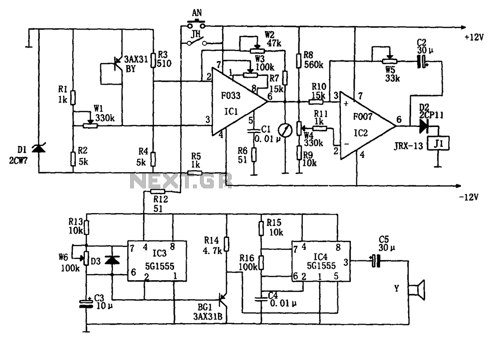
The temperature alarm circuit shown in the figure consists of an inverting amplifier (IC1), a comparison amplifier (IC2), a low-frequency multivibrator (IC3), a controllable oscillation frequency multivibrator (IC4), a bridge measurement network, a speaker (Y), and a power supply...

This document contains the complete wiring diagram for the Toyota Avanza. It is highly useful for technicians and car owners during service or maintenance activities. The wiring diagram includes the wiring for the Front Wiper and Washer, Headlight, ABS,...
The DD-2 is a highly regarded digital delay pedal that emulates an analog sound. It was initially sold from 1983 until it was discontinued in 1986, after which it was relaunched without any modifications as the DD-3 (noting that...
The AC welder operates intermittently, with power consumption during these periods reaching several hundred watts. The AC welder saving controller circuit enables the welding machine to automatically cut off power during no-load conditions while also automatically restoring power for...
This file is copyrighted. The individual who uploaded this work and first used it in licensing holds the rights. The provided information indicates that the file is protected by copyright, with the rights belonging to the individual who initially uploaded...