
High power siren circuit using CD40106

The circuit design employs the CD4046 IC, which functions as a phase-locked loop (PLL) frequency generator, providing a stable frequency output that can be easily modulated. The use of resistors R2, R3, R4, and capacitors C2, C3, and C4 establishes the timing and modulation characteristics, allowing for flexibility in the sound produced by the siren. The inclusion of ZD1 serves as a zener diode, providing voltage regulation to protect sensitive components within the circuit.
The transistors Q1 to Q6 are configured to create a push-pull output stage, which enhances the power delivered to the speaker, ensuring that the siren sound is sufficiently loud and effective for alerting purposes. The careful arrangement of these components on the PCB not only minimizes the overall footprint but also enhances thermal management and signal integrity, critical for maintaining performance in high-power applications.
For optimal performance, it is essential to ensure that all components are rated for the voltages and currents they will encounter during operation. The choice of speaker should match the specifications outlined (20 watts, 4-ohm or 8-ohm), as this will directly influence the sound output and efficiency of the siren.
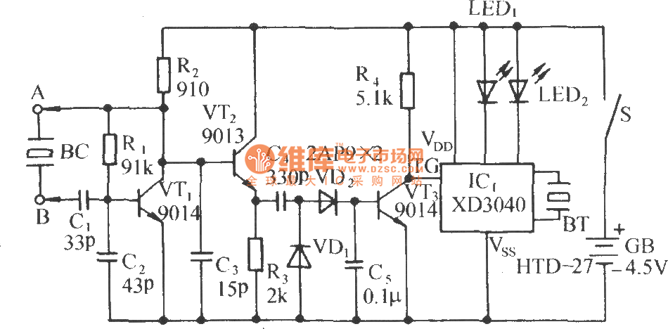
This compact siren circuit can be integrated into various alarm systems for applications such as home security, vehicle protection, or any scenario requiring a loud alert signal. Its efficient design allows for easy implementation in existing systems or as part of new security solutions, making it a versatile choice for enhancing safety measures.This is asimple siren sound that high power output and very noisy. ICs, Digital ICs are easy to use number CD4046 Inverter circuit and four transistor power increase current out to horn speaker 20 watt 4ohm 8ohm. Operation of the circuit when the circuit is connected to power. Frequency generator circuit starts, the cycle will be the second fr equency generator set to a first set of IC1 / 1, R2, C2 generator frequency 1Hz. Output can be modulated. With integrated suite 2, which is R3, R4, C3, ZD1 the modulation and frequency of Set 2 is the origin of IC1 / 2, R5, C4 are the output out of pin 12 of IC1 / 2 to Pin 1 of IC1 / 3. The output from the pin 2 is connected to IC1 / 4, IC1 / 5 and pin B of the Q1 output of IC1 / 4, IC1 / 5 is connected to pin B of Q2.
we can observe that Q1 and Q2 will run switch. Well, if work makes Q1 Q4, Q5 run a current through the speakers and will work if Q2 Q3, Q6 running a current flowing through the speakers. The nature of the circuit of Q3-Q6 will result in high currents flowing through the speakers, the sound of the siren is very loud.
As said at the beginning of the subject that. The PCB of the project have very small size just two stamps only. If not believe, then take a look at Figure 2. Really high efficient. Who wants to be redesigned to be smaller. Device should be soldered onto the PCB carefully, especially IC, transistors. And equipment such as polar Electrolytic capacitors, must be correct. Certifies that, this circuit of course works. This is a super siren is small. It can be applied compatible with various theft protection circuit, decidedly For example, to prevent a home burglary, car theft protection, or want to use a different alarm sirens. 🔗 External reference
Related Circuits
This precise one-pulse-per-second clock is constructed using a few common components and is driven by a 50 or 60 Hertz mains supply without a direct connection to it. An audible beep or a metronome-like click, along with a visible...

Active power factor correction stabilizes the electrical demand of a device to provide optimal power factor characteristics for various types of loads. To comply with power factor regulations, a cost-effective solution should be designed. In many applications, the requirement...
The circuit consists of a capacitance three-point oscillator, an isolation level, a voltage doubler rectifier circuit, a stereo sound circuit, and a flash display circuit. It can detect the quality of a crystal; a good crystal will emit a...

The generated alternating current (AC) at both ends of the voltage is adjusted after being rectified to supply the motor armature windings, allowing for speed adjustments of a 15W lamp. It is noteworthy that despite the freewheeling role of...

A switching power supply with an output voltage significantly lower than its input voltage exhibits an interesting characteristic: the current drawn by the supply is less than its output current. However, the input power (UI) is greater than the...

This portable AM/FM radio circuit is designed using the LA1800 integrated circuit (IC) along with several external components. The circuit diagram illustrates that the LA1800, manufactured by Sanyo Semiconductors, requires only a few additional components. The output signal is...