
Adjustable power charger circuit
The charging apparatus is designed to efficiently manage the charging process for multiple battery configurations. The adjustable output voltage and current provide flexibility for various battery chemistries and capacities. The use of a double-base diode and an oscillator circuit enhances the control over the charging process, allowing for precise adjustments to ensure safe charging conditions. The inclusion of sampling and damping components further ensures that the charging operation is stable and reliable.
The transformer selection is critical, as it needs to provide sufficient power while maintaining the required voltage levels. When selecting a transformer, it is important to consider the output voltage and current ratings to ensure compatibility with the charging requirements. Additionally, the use of a thyristor for current control allows for efficient switching and regulation of the charging current, which is essential for protecting the battery from overcharging.
The operational sequence emphasizes safety and efficiency, highlighting the importance of connecting the battery before powering on the device and disconnecting it only after the power has been turned off. This practice minimizes the risk of electrical arcing and potential damage to both the apparatus and the battery.
Interference with the grid can be a significant issue, particularly in sensitive electrical environments. Implementing a filtering solution, such as an RLC filter or a ferrite bead, can help mitigate these effects, ensuring that the charging apparatus operates within acceptable limits without disrupting other electrical devices.
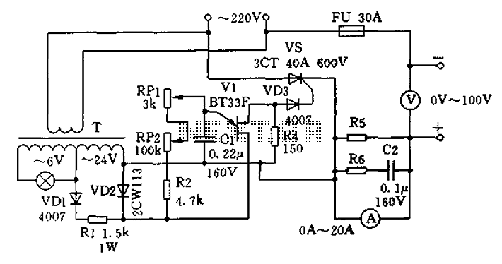
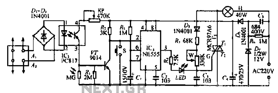
Overall, this charging apparatus is a versatile solution for battery management, capable of handling various configurations and providing adjustable charging parameters to accommodate different battery types and sizes. Proper implementation and component selection will enhance its performance and reliability in practical applications. Charging apparatus shown in schematic circuit, the maximum output current of 20A, the maximum charge voltage of 80V. It can be adjusted from 0V onwards, and therefore capable o f a variety of battery charging, the battery pack can also be connected in series or battery of the same size charging, such as up to five 12V batteries in series for charging at the same time. Pair of series battery charging can shorten the connection length, reduce line losses, convenient connection, it can greatly improve efficiency.
From the figure, the transformer T is double-base diode voltage V1 to provide work, double-base diode V1 and the corresponding peripheral components of an oscillator, the oscillation frequency can be RP1, RP2 control. In this circuit, RP1, RP2 value difference between the larger, so in practical work, RP2 can play the role of coarse, RP1 from fine-tune the role of a single battery charge when it is particularly important to avoid damage to the battery.
V1 generated by the oscillation pulses through VD3 isolation triggered thyristor VS, charging current and voltage level depends on the size of the oscillator output pulse, which is determined by the oscillation frequency. R5 is a sampling resistor, depending on meter size may be, if the internal resistance ammeter with the sampling, the R5 can be omitted.
R6, C2 is to protect the head of the table with a damping element. The actual selection of component parameters as shown, available power transformer T is 5W, the output voltage of about 24V any type of transformer, if the output voltage of less than 0 ~ 80V, maximum current up to less than 20A, can be replaced with another double base tube can also be replaced with higher sensitivity triggered thyristor. Of particular note are: phase and neutral connection according to the figure; the actual operation, must be connected before power is turned on after the battery; When charging is completed, you should cut off the power, then remove the battery connections.
The disadvantage of this machine is significant interference on the grid, able to do so, you can make a powerful filter to reduce interference on the power grid.
Related Circuits

The simple pulse width modulation circuit is illustrated in the figure. It utilizes an operational amplifier to create a multivibrator, resulting in a symmetrical oscillation output signal with a duty cycle of 50%. By adjusting the external threshold voltage,...
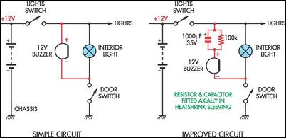
Two headlight reminder circuits are designed for easy installation and operation based on the KISS (Keep It Simple Stupid) principle. The basic circuit consists of a 12V piezo buzzer connected between the lights circuit and a door switch. The...
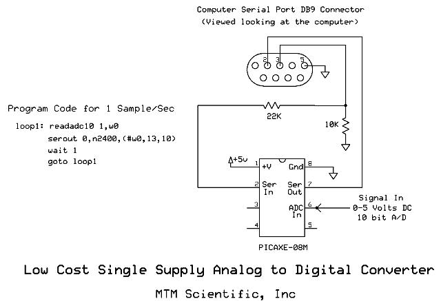
Collecting and storing experimental data presents a common challenge for hobbyists. A widely used method involves utilizing a device that converts analog data into digital format and stores the information on a computer. These devices are known as A/D...
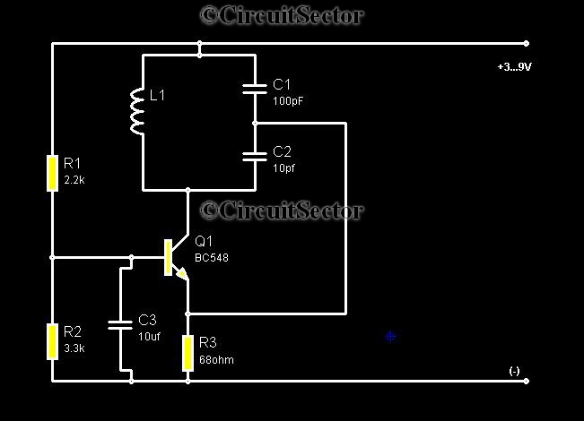
Metal detectors are typically complex devices that often incorporate expensive components, making DIY metal detector circuits uncommon. However, this metal detector hobby circuit can be built using only a few components, such as a BC548 transistor and a standard...
The Ai. A2 series operates with a telephone line, where sound anomalies or off-hook currents activate a light within an arc tube, which in turn triggers a photosensitive MOSFET. This process involves a saturated conduction base voltage that sends...
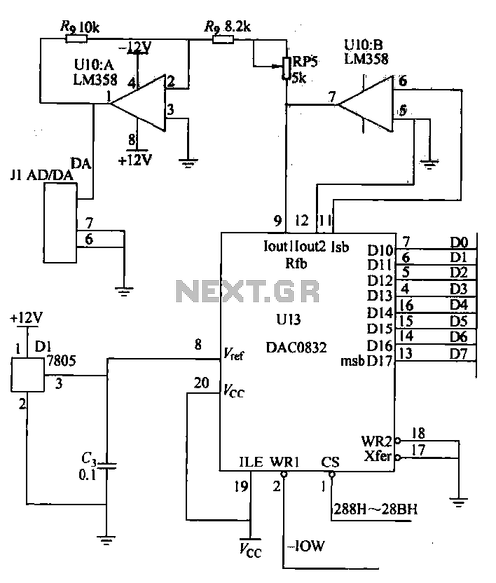
A digital-to-analog (D/A) conversion circuit utilizing the DAC0832 and the operational amplifier LM358, featuring two output channels with unipolar voltage output. The digital input range is from 00H to FFH, which corresponds to an output voltage range of 0V...
Warning: include(partials/cookie-banner.php): Failed to open stream: Permission denied in /var/www/html/nextgr/view-circuit.php on line 713
Warning: include(): Failed opening 'partials/cookie-banner.php' for inclusion (include_path='.:/usr/share/php') in /var/www/html/nextgr/view-circuit.php on line 713