
DA conversion circuit
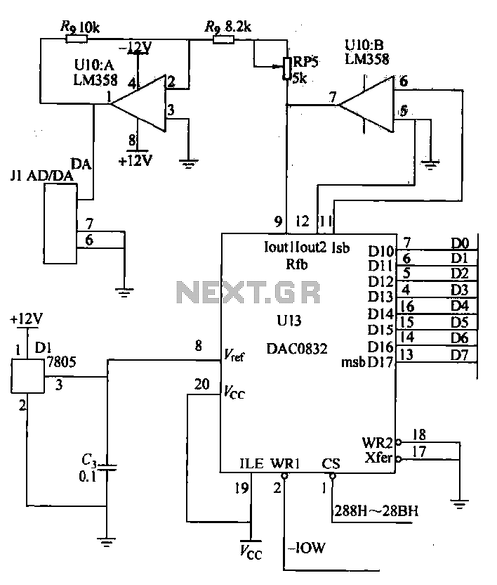
The circuit described employs the DAC0832, a 8-bit digital-to-analog converter, which converts digital signals into corresponding analog voltages. It accepts digital input in binary form, ranging from 00H (0 in decimal) to FFH (255 in decimal). The output voltage is linear and unipolar, spanning from 0V to 5V, which is suitable for various applications, particularly in PID control systems for temperature regulation.
The operational amplifier LM358 is utilized in this circuit to amplify the output from the DAC0832. The first stage of the operational amplifier is configured to provide a bipolar output that ranges from 0V to -5V. This configuration allows for the adjustment of the output signal to meet specific application requirements. The second stage of the operational amplifier further processes the signal, providing a unipolar output that ranges from 0V to +5V, thereby ensuring compatibility with the control system.
The reference voltage for the DAC0832 is supplied by a 7805 voltage regulator, which stabilizes the voltage at +5V. This regulated voltage is crucial for maintaining accuracy in the D/A conversion process. The DAC0832 is addressed within a specific range (288H to 28BH), allowing for easy integration into larger systems where multiple devices may be controlled.
In the context of a digital PID controller, this circuit is employed to manage the temperature of an electrical resistance furnace. The digital PID controller processes input signals and adjusts the output to maintain the desired temperature. For instance, a digital input of 200 corresponds to an output voltage of 5V, indicating a specific setpoint for the furnace temperature.
Overall, this D/A conversion circuit is a critical component in applications requiring precise analog outputs from digital inputs, particularly in temperature control systems where accuracy and stability are paramount.D/A conversion circuit by the DAC0832 and op amplifier LM358, etc., there are two bad-out channel, unipolar voltage output. Digital output range: OO-H FFH, corresponding to an output voltage range; O Sv. Digital PID controller is plowing ox horn control bi cents. Electrical resistance furnace temperature control, which corresponds to 5v 200. ov corresponds to 0. DAC0832 address is 288H ~ 28BH, then the reference voltage regulator block 7805 output + 5v, before an operational amplifier output out of o ~ - 5v. The second stage of the operational amplifier output is o- + 5v.
Related Circuits
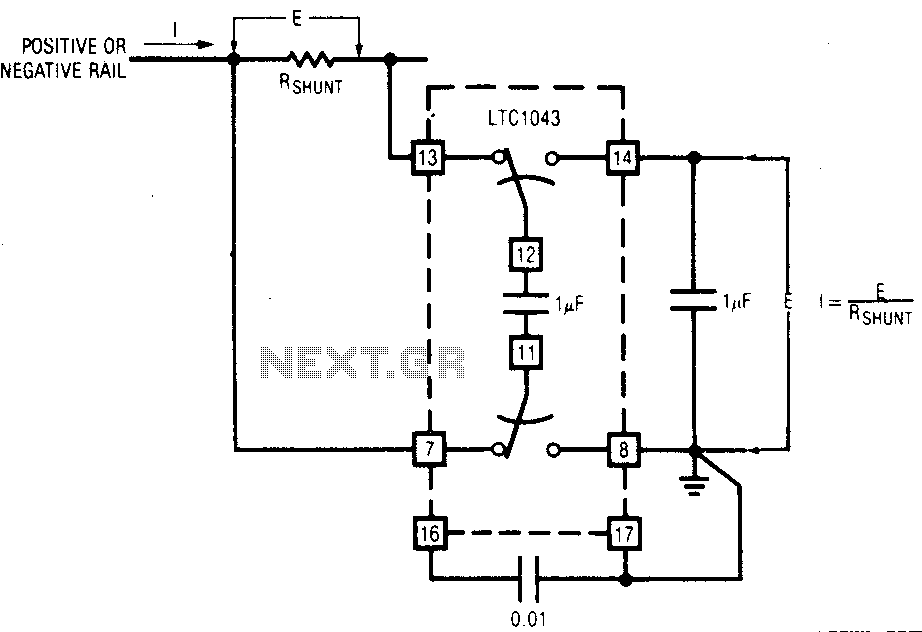
The LTC1043 can be induced through any of its current shunt supply rails. Many cells and solar system applications have this feature. If the reference point is grounded, the voltage output of an unloaded amplifier is minimal, allowing the...
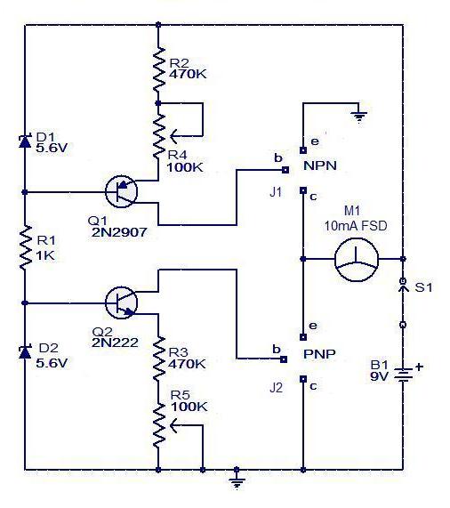
The circuit for a transistor tester is a relatively simple device. The transistor tester circuit illustrated below can be utilized to measure and identify the pins of a transistor, as well as determine its condition. Furthermore, this circuit can...
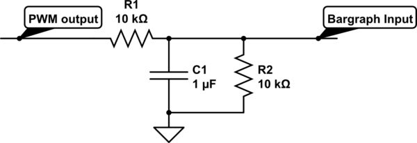
For a project, there is a need to display a progress bar representing the activity performed by a microcontroller unit (MCU). A bar graph display is intended for this purpose; however, the bar graph display driver IC, LM3914, requires...
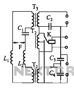
Tubular xenon lamp power, high brightness, known as the "little sun." Tubular xenon lamp wiring is illustrated in Figure 2-6. The tubular xenon lamp is a high-intensity discharge (HID) light source, characterized by its ability to produce a bright white...
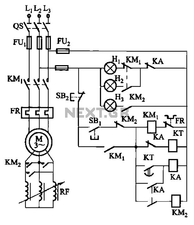
The circuit depicted in Figure 3-165 utilizes a time relay (KT) for controlling the start-up time. Indicator light Hi serves as the power indicator, H2 is designated for the start lights, and H3 functions as the running lights. The circuit...
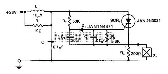
The LRC input network limits the anode dv/dt to a safe value below 30 V/μs. Rl provides critical damping to prevent voltage overshoot. While a simple RC filter section could be used, the high current required by the squib...
Warning: include(partials/cookie-banner.php): Failed to open stream: Permission denied in /var/www/html/nextgr/view-circuit.php on line 713
Warning: include(): Failed opening 'partials/cookie-banner.php' for inclusion (include_path='.:/usr/share/php') in /var/www/html/nextgr/view-circuit.php on line 713