
Adjustable Strobe Light
The Adjustable Strobe Light circuit utilizes a high-intensity "horse shoe" Xenon flash tube, which is capable of producing a significant amount of light output compared to standard strobe lights. The flash rate of this circuit can be adjusted up to approximately 20 Hz, allowing for versatile applications in various lighting scenarios.
Key components of the circuit include a transformer (T1) and an inductor (L1), both of which are available for purchase from The Electronics Goldmine. The circuit design is not isolated from ground, necessitating caution during operation, particularly when the device is not housed in a protective enclosure. It is imperative to use a case during normal operation to prevent accidental contact with high-voltage components.
The circuit employs capacitors C1 and C2, which store energy for the flash tube. It is critical to monitor the operation of the circuit, as excessive use at high flash rates—specifically beyond 30 seconds—can lead to overheating of these capacitors, potentially resulting in failure or explosion.
Diodes used in the circuit should be rated for at least 250 volts and 1 amp to ensure reliable operation. While the schematic does not include an on/off switch, it is advisable to integrate one into the design for enhanced user control and safety.
Overall, this Adjustable Strobe Light circuit offers advanced features and flexibility for users, but it requires careful handling and adherence to safety precautions to ensure reliable and safe operation.This Adjustable Strobe Light is the bigger brother of the plain old strobe light. This one uses a much more powerful "horse shoe" Xenon tube which produces more light. You can also control the flash rate up to about 20Hz. Do not look directly at the flash tube when this thing is on! # T1 and L1 are available from The Electronics Goldmine (see Where To Get Parts). This ciruits is NOT isolated from ground. Use caution when operating without a case. A case is required for normal operation. Do not touch any part of the circuit with the case open or not installed. Most any diodes rated at greater then 250 volts at 1 amp can be used instead of the 1N4004`s. Do not operate this circuit at high flash rates for more than about 30 seconds or else C1 and C2 will overheat and explode. There is no on/off switch in the schematic, but you can of course add one. 🔗 External reference
Related Circuits
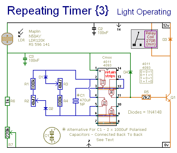
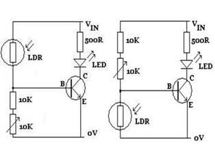
This circuit closely resembles Repeating Timer No. 2. However, the inclusion of a light-dependent resistor (LDR) allows the timer's operation to be confined to daylight hours. Resistor R7 enables the adjustment of the light level at which the timer...

When the tank is cleaned the fish are removed and placed in a small amount of the tank water. The problem is that fish don’t like rapid temperature fluctuations. A simple in-tank or stick-on thermometer would have sufficed, but...
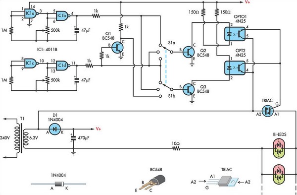
This circuit utilizes low-voltage AC to power a string of approximately 50 bi-color LEDs, with two LEDs connected in inverse parallel. The power supplied to the LEDs is managed by a Triac and two optocouplers, whose phototransistors are also...
Currently, white LEDs are available that emit a significant amount of light. Their brightness is such that direct eye contact should be avoided. Although they are still relatively expensive, this is expected to change in the future. A highly...
The figures above illustrate the fundamental concept of a robot, which consists of various input and output devices connected to a central processing unit, commonly referred to as the brain. These inputs and outputs are essential for the robot's functionality...
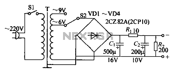
The adjustable current power supply circuit operates at 6V and 9V, utilizing a minimal number of components, which facilitates easy assembly. The circuit can deliver an adjustable output current of up to 100mA, serving as a suitable alternative to...