
Using AC for LED Christmas Lights

This circuit design effectively demonstrates the use of low-voltage AC to control bi-color LEDs, leveraging the characteristics of a Triac and optocouplers for dynamic color display. The choice of bi-color LEDs allows for versatile color combinations, as the LEDs can emit red, green, or blended colors depending on the AC signal applied. The Triac acts as a switch that can control the flow of AC current to the LEDs, making it suitable for applications requiring efficient power management and color modulation.
The optocouplers serve to isolate the control signals from the high-voltage AC circuit, enhancing safety and preventing interference from the main power line. Each optocoupler is configured to activate the Triac in response to its respective input signal, effectively allowing for the independent control of each LED color. The inverse parallel connection of the optocouplers and LEDs ensures that when one color is activated, the other is turned off, thus achieving the desired color output.
The switch S1 plays a crucial role in determining the operational mode of the circuit. By selecting between the outputs of the two oscillators, which are built using NAND gates from the 4011B integrated circuit, various flashing patterns can be achieved. This feature adds a layer of versatility to the circuit, making it suitable for decorative lighting applications, visual indicators, or any scenario where dynamic color effects are desired. The configuration of the NAND gates allows for the generation of different frequencies and duty cycles, further enhancing the range of patterns that can be produced.
Overall, this circuit exemplifies an efficient and flexible approach to LED color control using low-voltage AC, showcasing the interplay between digital logic and analog components to create visually appealing lighting effects.This circuit uses low-voltage AC to drive a string of 50 or so bi-color LEDs (two LEDs connected in inverse parallel). Power to the LEDs is controlled by the Triac and the two optocouplers which have their photo-transistors effectively connected in inverse-parallel.
Depending on which optocoupler is turned on, the Triac applies positive, negative or both half-cycles to the LEDs and so the colours can be red, green or in-between. Switch S1 is used to select the pulses from two oscillators which are formed by the NAND gates in IC1 (4011B). This provides a variety of LED flash patterns, depending on the setting of S1. 🔗 External reference
Related Circuits
Climber A ascends a route while Climber B remains on the ground, tracking Climber A's progress with a laser pointer. The Redpointer device records the exact route taken. In Mode 1, the recorded route is played back in real-time,...

The circuit consists of dual drive integrated circuits (ICs) utilized in a 10 LED level meter configuration. The schematic features two TLM8101 driver ICs, which can be employed as alternatives. The 10 LED level meter circuit is designed to provide...
The circuit illustrates a straightforward triangle and square wave generator utilizing a common dual operational amplifier, the LM1558, capable of producing very low frequencies around 10 kHz. The time interval for one half-cycle is approximately determined by the product...

A PC’s serial port provides signal lines that you can use to expand the number of input signals. With some additional circuitry tied to these lines, you can use the port to test digital TTL logic-level circuits. You just...
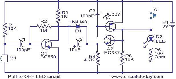
This circuit features an LED that can be turned off with a puff of air. A condenser microphone (M1) detects the puff. When the push button switch S1 is activated, transistors Q2 and Q3, configured as a latching pair,...
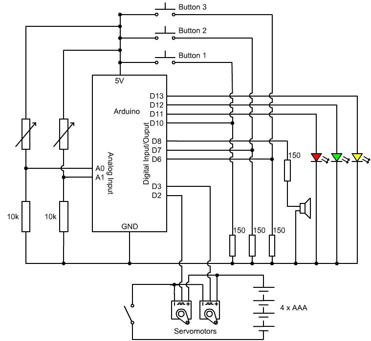
In various industrial processes, it is essential to rotate a DC (or AC) motor both forward and reverse for a specified duration. Initially, the motor rotates forward (clockwise) for a certain period (approximately 2 to 3 minutes), then stops...
Warning: include(partials/cookie-banner.php): Failed to open stream: Permission denied in /var/www/html/nextgr/view-circuit.php on line 713
Warning: include(): Failed opening 'partials/cookie-banner.php' for inclusion (include_path='.:/usr/share/php') in /var/www/html/nextgr/view-circuit.php on line 713