
adjusting Williamson amp
The discussion revolves around the performance evaluation of different amplifier configurations, particularly focusing on the pentode connection and the Mullard 5-10 circuit. The Mullard 5-10 is a well-known audio amplifier design that utilizes a push-pull configuration with a pair of EL84 output tubes in a class AB operation. This design is often praised for its warm sound and efficient power output, but it may not deliver the highest fidelity compared to other configurations.
In a pentode-connected amplifier, the pentode tube offers higher gain and better linearity compared to a triode. However, the trade-off can include increased distortion levels and a more complex feedback network to maintain sound quality. The Mullard 5-10, while not optimal in every aspect, provides a balanced performance that appeals to many audio enthusiasts.
To analyze the circuit, it is essential to consider the input stage, which typically consists of a low-noise transistor or a triode, followed by a phase splitter that drives the output stage. The output stage, featuring the EL84 tubes, is coupled to the speaker through output transformers, which are crucial for impedance matching and ensuring efficient power transfer. The feedback loop in the Mullard design is implemented to reduce distortion and stabilize the gain, which is a critical aspect of achieving desired sound characteristics.
In summary, while the pentode connection may offer specific advantages in terms of gain and linearity, the Mullard 5-10 circuit design presents a well-rounded approach to audio amplification that balances performance with practicality, making it a popular choice among audiophiles.Originally Posted by artosalo My original claim was that pentode connected version is not optimum. NO! You wrote the Mullard 5-10 is not optimum. If.. 🔗 External reference
Related Circuits

This project involved the design of an audio amplifier that delivers substantial output power while maintaining a minimal parts count and high quality. The power amplifier section utilizes only three transistors along with a few resistors and capacitors arranged...
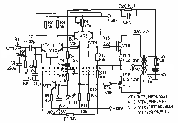
This article describes a transformer-based output FET amplifier, with tonal characteristics similar to those of tube amplifiers. It introduces various effects that are significant for audio enthusiasts. Power amplifier specifications include a rated output power of 50W (with an...
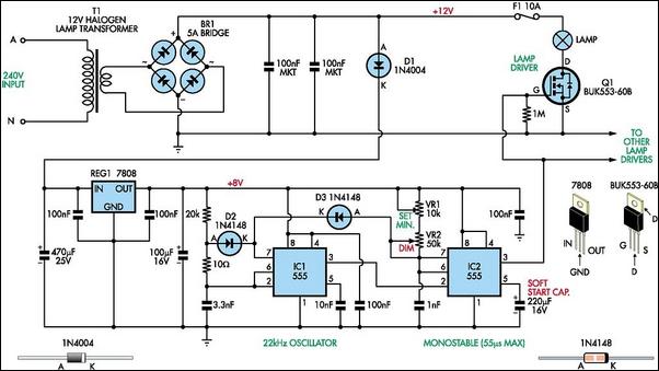
Most dimmers utilize pulse width modulation (PWM) to regulate the power supplied to the lamp. Those that include a switch faceplate manage the firing angle of a Triac on the 240V mains side. While these dimmers work effectively with...
A request for a DIY 300BSE power amplifier schematic is made, with a specification to utilize Lowther PM6 speakers. The 300BSE power amplifier is a well-regarded audio amplification circuit known for its warm sound and high fidelity, particularly suited for...
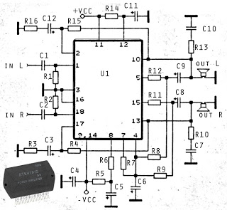
The circuit described is a stereo amplifier utilizing the STK4191 integrated circuit, providing an output power of 2 x 50 Watts at an 8-ohm impedance. Additionally, various other ICs in this series can be utilized, including the STK4101, STK4111,...
This diagram represents a schematic of an RF amplifier circuit. The circuit is designed to amplify an RF signal from approximately 100 mW input power to 1.3 W output power. It utilizes a general NPN RF transistor, specifically the...