
ADT70 platinum resistance temperature measurement circuit
The AD170 is a precision temperature measurement device that is particularly well-suited for applications requiring high accuracy and stability over a wide temperature range. The integration of a voltage source, current source, and amplifier within the ADT70 simplifies the design of the temperature measurement circuit, minimizing the need for additional external components. This integration allows for a more compact and efficient design, reducing potential points of failure and enhancing reliability.
In the described PRTD configuration, the 4-wire setup is crucial for eliminating errors due to lead resistance, which can significantly affect measurement accuracy in lower resistance sensors. By using two wires for the measurement and two for the current supply, the circuit can effectively cancel out the resistance of the lead wires, ensuring that the measurement reflects only the resistance of the platinum sensor itself.
The reference resistor R is carefully selected to match the output current of the current source, ensuring that the system operates within its specified parameters. The outputs OUTA and OUTB are connected to the instrumentation amplifier, which is designed to amplify small differential signals. The instrumentation amplifier's high input impedance prevents loading of the sensor and allows for accurate signal processing.
The gain of the instrumentation amplifier is adjustable via the external resistor Rc, providing flexibility in the circuit design to accommodate various measurement ranges and sensitivities. This feature is particularly advantageous in applications where different temperature ranges may need to be monitored without redesigning the entire circuit.
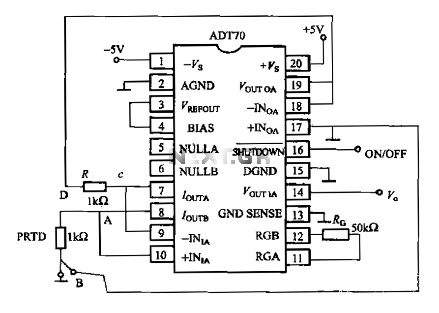
Overall, the AD170 and its associated circuitry represent a robust solution for precision temperature measurement, combining ease of use with high performance, making it suitable for a variety of industrial and laboratory applications.AD170 basic electrical parameters are as follows: temperature coefficient of 25ppm/C, temperature measurement accuracy of l, the maximum temperature in the range of a 200 ~ + I OOOqC, the power supply + 5v or t5v, operating temperature range of -40- + 125 C. ( 1) PRTD platinum resistance temperature measurement circuit. Since ADT70 internal integration of the voltage source, a current source and amplifier, because this use it as a measuring temperature, the external circuit is very simple, as shown in Figure 1-47 is ADT70 platinum RTD temperature measurement circuit. PRTD 4-wire (2-wire one end respectively connected to + INIA,/OUTB, 2 lines are grounded and the other end of the op amplifier of ?
feet) platinum resistance thermometer, R is the reference resistor, matching current source output current, OUTA,/OUTB are applied to the reference resistance test, instrumentation amplifier - UNIA and platinum resistance, the instrumentation amplifier + on INIA, platinum resistance thermometer output signal simultaneously. after the op amp and instrumentation amplifier amplifies the output pin ? instrument gain of the amplifier by the variable external resistor Rc decision G 49. 9kfl/Rc
Related Circuits
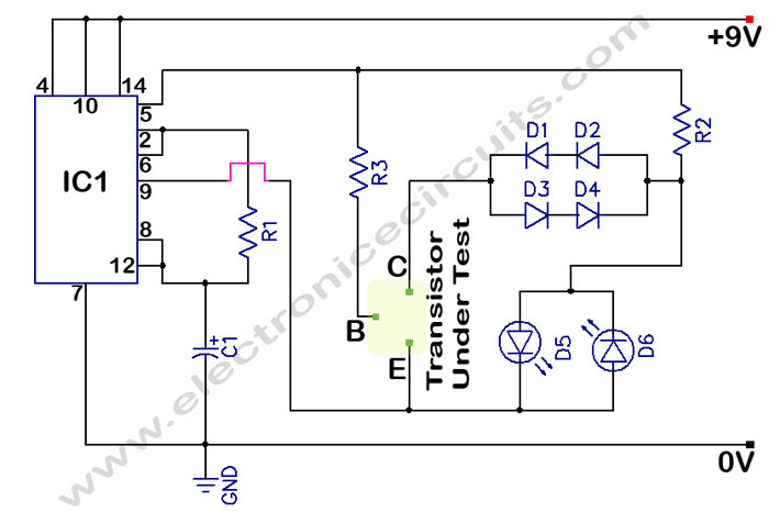
The circuit is a transistor tester schematic that indicates the condition of a transistor using two LEDs. It is designed to test a good NPN transistor. The transistor tester circuit operates by utilizing two light-emitting diodes (LEDs) to provide a...
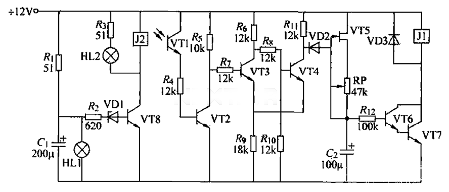
A blocking material monitoring circuit is presented. When the optical path is obstructed by the material, the phototransistor VT1 turns off, which subsequently turns off transistors VT2, VT3, and VT4. This arrangement is coupled to a flip-flop configuration. When...
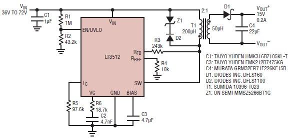
A straightforward dual 15-volt power supply electronic circuit can be created using the LT3512 switching regulator IC produced by Linear Technology. This basic 15-volt DC power supply operates with an input voltage range of 36 to 72 volts and...
The primary function of the optical receiver is to extract information encoded on a modulated light carrier from a distant transmitter and restore it to its original form. A typical through-the-air communications receiver can be divided into five distinct...
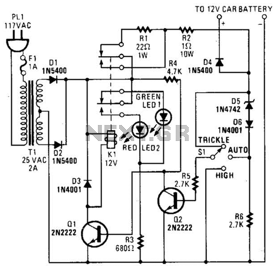
The circuit is capable of supplying either a trickle charge (50 mA) or a high-current charge (1 A). Users can select either charging method or an automatic mode that initially trickle charges a battery if it is particularly low...
The micropower circuit automatically provides shutdown, power-up, and low-battery lockout functions without requiring software or operator control. The micropower circuit is designed to manage power efficiently in battery-operated devices, ensuring optimal functionality while conserving energy. The shutdown feature is activated...
Warning: include(partials/cookie-banner.php): Failed to open stream: Permission denied in /var/www/html/nextgr/view-circuit.php on line 713
Warning: include(): Failed opening 'partials/cookie-banner.php' for inclusion (include_path='.:/usr/share/php') in /var/www/html/nextgr/view-circuit.php on line 713