
Thermometer with 10 LED scale
The LED thermometer circuit utilizes the LM34DZ precision temperature sensor, which is capable of measuring a wide temperature range from -50°F to +300°F, though the specific design is optimized for a narrower range of approximately 60°F to 78°F. The circuit employs the LM3914 Bar/Dot Graph Driver IC (U2) to visually represent the temperature reading through a series of ten LEDs (D1 to D10). The choice of LEDs can affect the visibility and aesthetic of the thermometer; blue LEDs, while modern in appearance, may require higher forward voltage and could appear dimmer compared to other colors such as red, yellow, or green.
The circuit requires careful calibration to ensure accurate temperature readings. It is advisable to use sockets for U1 (LM34DZ) and U2 (LM3914) to facilitate easy removal during the calibration process. The calibration involves adjusting several potentiometers (R2, R5, R7) and resistors (R1, R3, R4, R6, R8) to achieve the desired voltage output corresponding to the temperature range. Specifically, R8 can be adjusted based on the operating mode of U2; when pin 9 is left disconnected, the circuit operates in dot mode, necessitating a 100 Ohm resistor, while connecting pin 9 to 9V switches the operation to graph mode, requiring a 15 Ohm resistor.
Capacitors C1 and C2 are included to stabilize the power supply and filter any noise, ensuring the sensor operates effectively. The circuit's power supply should be stable, and a voltmeter is essential for the calibration process to measure the voltages at specific pins of U2. The calibration steps involve adjusting the trim pots and resistors to match the expected voltages, which correspond to the temperature readings. After calibration, the resistors must be set accurately, particularly R1, which should be three times the resistance measured for R3.
In summary, this LED thermometer circuit is a practical application of electronic components to create a user-friendly temperature sensing device, combining precision measurement with an intuitive visual output. Proper assembly and calibration are crucial for achieving reliable performance.This LED thermometer is designed for in home use, to read temperatures between about 60 and 78 degrees Fahrenheit. It is based around a precision temperature sensor IC, the LM34DZ. This sensor require no calibration and can measure temperatures of between -50F and +300F. While the circuit shown here does not use the full range of that sensor, it can be modified to do so by simply changing the voltage reference to U2 at the sacrifice of precision.
You will want to build the circuit with U1 and U2 in sockets in order to be able to complete calibration (which requires removal of these ICs). You can use any LED you want for D1 - D10, however blue LEDs have a higher voltage requirement so if you want to go blue for a modern look, they may appear more dim then red, yellow or green.
C1 1 1uF 25V Electrolytic Capacitor C2 1 10uF 25V Electrolytic Capacitor R1 1 2.2K 1/4W Resistor R2, R5, R7 3 1K Trim Pot R3 1 1K 1/4W Resistor R4 1 1.5K 1/4W Resistor R6 1 470 Ohm 1/4W Resistor R8 1 100 Ohm Or 15 Ohm 1/4W Resistor (See Notes) D1 - D10 10 LED U1 1 LM34DZ Precision Fahrenheit Temperature Sensor U2 1 LM3914 Bar/Dot Graph Driver IC MISC 1 Board, Wire, Socket For U1 and U2, Case By leaving pin 9 of U2 disconnected, the graph will operate in dot mode and R8 should be 100 Ohm. If you build the circuit with pin 9 tied to 9V, the circuit will be in graph mode and R8 should be 15 Ohms.
To calibrate the circuit, you will need a voltmeter. Power the circuit up and let it sit for a few minutes for temperature to stabilize. Ground the negative lead of the meter and connect the positive lead to pins 6 and 7 of U2. Set R7 so the meter reads as close to 3.345V as possible. Now connect the positive lead of the meter to pin 4 of U2 and adjust R5 until the meter reads 2.545V. Finally, disconnect power to the circuit and remove U1 and U2 from their sockets. Measure the value of R3 with an ohmmeter and remember that value. Connect the ohmmeter across R1 and adjust R1 to a value of exactly 3 times the value of R3. Reinstall U1 and U2 and the circuit is ready for use. 🔗 External reference
Related Circuits
A simple LED-based voltmeter is required to monitor the voltage of a variable power supply. The proposed LED voltmeter circuit utilizes a series of light-emitting diodes (LEDs) to visually represent the voltage level of a variable power supply. This...
This indicator can be used, or see if your speakers can be damaged by the noise power. With P1 you can set the limit to which D1 LED lights. The pot is 100k here, you can even experiment with...
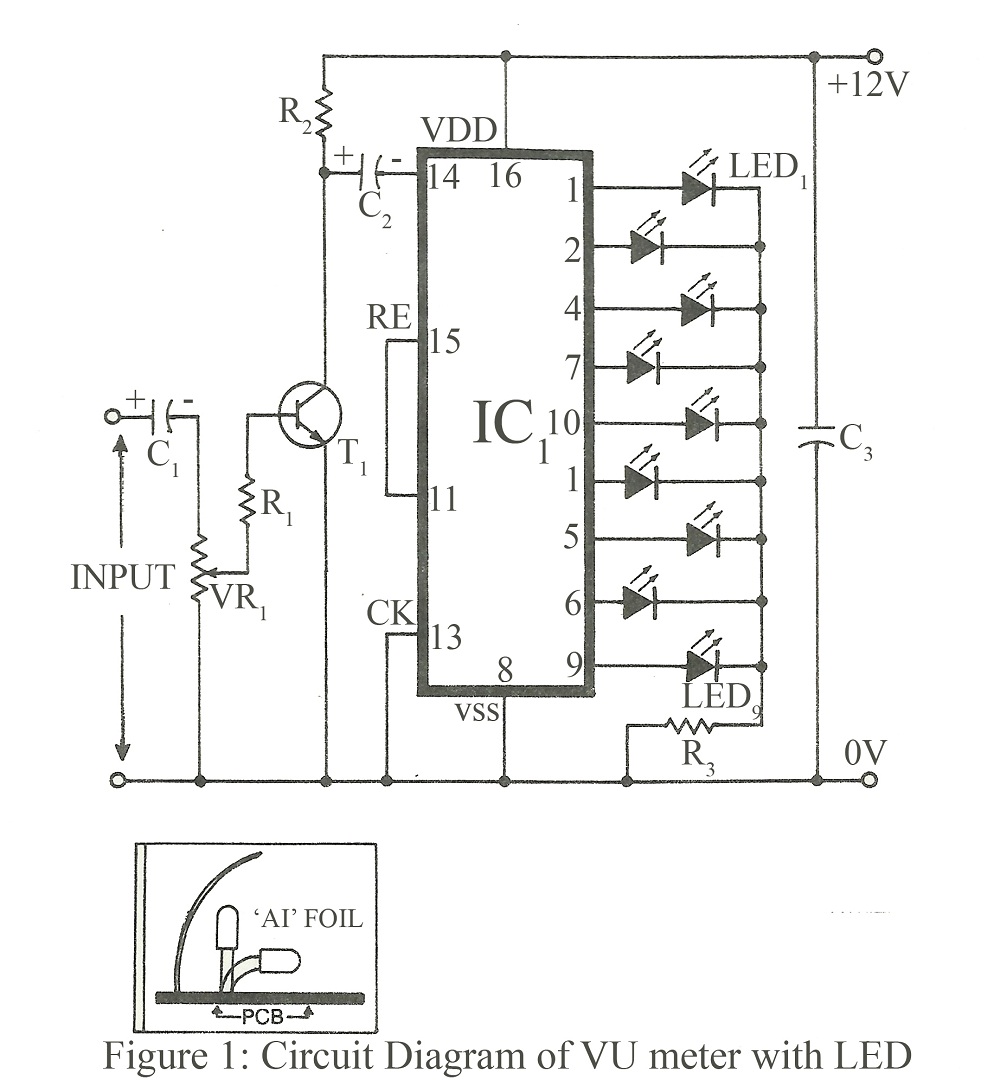
When constructing a stereo amplifier or if one is already owned, it is beneficial to incorporate this circuit. The entire setup is based on the IC4017, with its clock input connected through a BC107 transistor. The IC4017 functions as...

The TL082 (Or a TL072 also is OK) Creates an Adjustable Sawtooth Generator. (It also has a Square wave Output, but it isn`t used here.) The Left and Right LEDs are connected in series, and if this circuit is used...
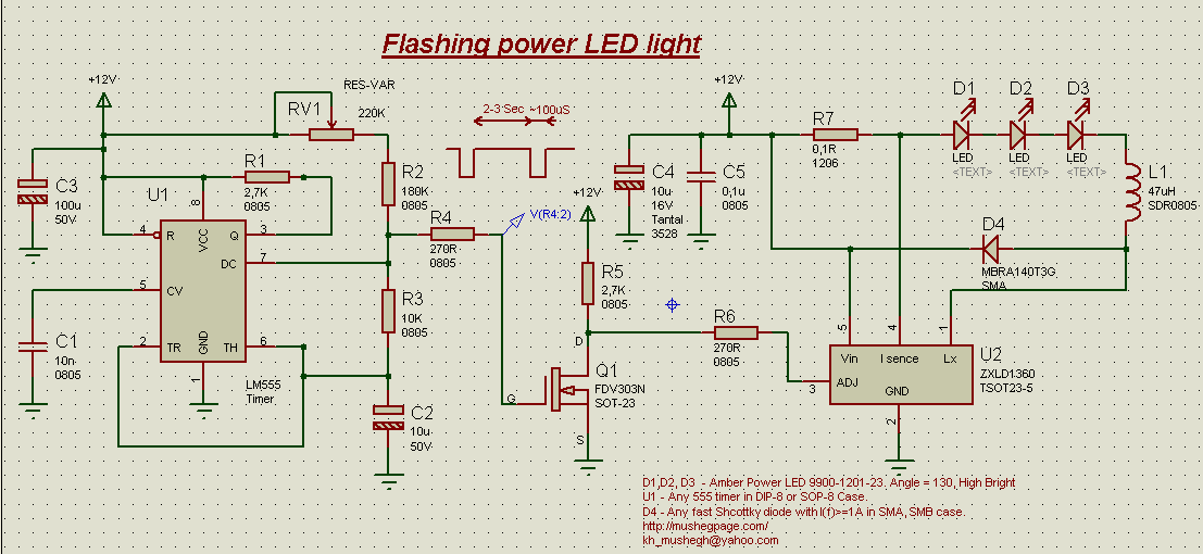
This project demonstrates the construction of a simple flashing light circuit using the IC 555 timer. The 555 timer functions as a clock generator with a duty cycle of less than 100% and greater than 50%. Additional components include...
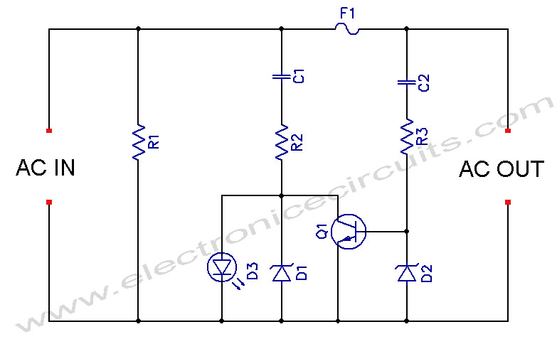
LED Blown AC Fuse Indicator Circuit Diagram. This circuit monitors an AC fuse. In this circuit, the LED indicator shows whether or not the fuse is blown. The LED Blown AC Fuse Indicator Circuit is designed to provide a visual...