
LED ramping circuit
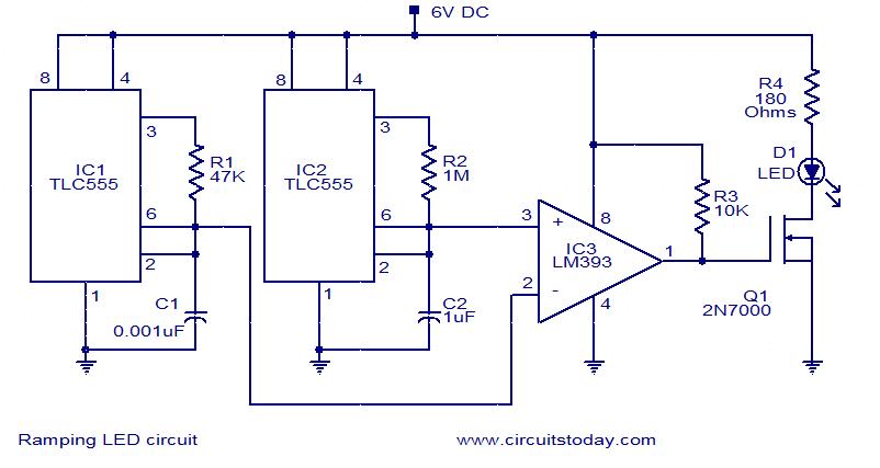
This circuit effectively utilizes the 555 timer ICs to create a dual-frequency output necessary for modulating the brightness of the LED. The first 555 timer (IC1) generates a high-frequency square wave at 10 kHz, which is essential for rapid switching, while the second timer (IC2) produces a low-frequency square wave at 1 Hz, which dictates the overall modulation speed of the LED brightness.
The LM393 operational amplifier acts as a comparator, receiving the outputs from both timers. The comparator's role is to compare these two frequency signals and generate a pulse-width modulation (PWM) output. This PWM signal varies in duty cycle, which directly influences the average power delivered to the LED.
Field-effect transistor Q1 is employed to handle the higher current required by the LED. The PWM signal from the LM393 controls the gate of Q1, allowing it to switch the LED on and off rapidly. The result is a smooth transition in brightness, as the LED ramps up to full brightness and then dims back to OFF. The time constants of the 555 timers, along with the resistor R4, can be adjusted to fine-tune the LED's brightness ramping speed and overall current flow, ensuring optimal performance and longevity of the LED.
This circuit design is particularly useful in applications requiring visual indicators with gradual brightness changes, such as in decorative lighting, automotive lighting, or user interface elements in electronic devices.In this circuit the intensity of LED will vary in a ramping fashion. The circuit consists of three ICs: Two 555 timer ICs and one LM393 op-amp. IC1 and IC2 are wired as oscillators to produce 10 KHz and 1 Hz frequencies respectively. These two frequencies are given to the inputs of the op-amp LM393. LM393 is wired as a comparator and its output will be a PWM signal. This PWM signals controls the FET Q1 to drive the LED. The LED will rise from OFF state to full brightness slowly and then slowly fades to OFF state and this operation repeats. The resistor R4 controls current through the LED. 🔗 External reference
Related Circuits
The circuit contributes 3.2 nV/√Hz of voltage noise and 0.45 pA/√Hz of current noise. To minimize noise from other sources, resistor R3 is configured to 100 ohms, resulting in an additional voltage noise of only 1.3 nV/√Hz. Resistors R1,...
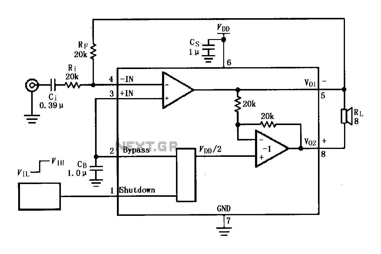
The LM4819 audio power amplifier is designed to amplify audio signals. An audio signal is input through the coupling capacitor (Ci) and the resistor (Ri) applied to the inverting input terminal (pin 3) of the amplifier. The inverting input...
These two tank circuits appear to broaden the operating spectrum. The accompanying information sheet indicates that when both circuit stages oscillate at the same frequency, the power output reaches its maximum. This suggests that if the tunable tank circuit...
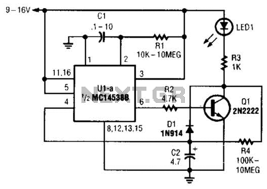
When power is first applied to the circuit, capacitor C2 begins to charge through LED1, resistor R3, and resistor R4. When the voltage across C2 reaches the input trigger level of operational amplifier U1, the output at pin 6...
The metal detector circuit consists of several key components including the probe oscillator, reference oscillator, oscillation signal processor, mixing amplifier, and ammeter PA. The probe oscillator is made up of the oscillating tube VI, exploration coil L1, capacitors C1...
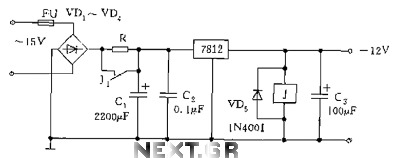
The figure below illustrates the use of a relay in the starting circuit. The power input connects through a resistor R, which serves two purposes: first, it prevents a large current from the capacitor C1 from affecting the power...