
Advanced Triangular wave generator
The triangular wave generator is an essential component in various electronic applications, including signal processing, waveform generation, and testing. This circuit typically utilizes operational amplifiers (op-amps) or comparators to create a stable triangular waveform.
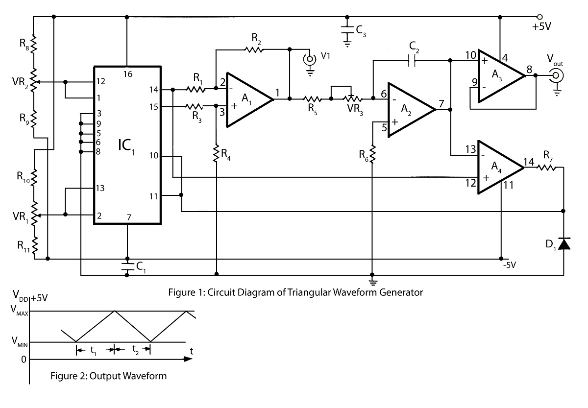
The core functionality of the triangular wave generator involves charging and discharging a capacitor through a resistor. The charging phase occurs when the capacitor is connected to a voltage source, causing it to ramp up linearly until it reaches the maximum peak level. At this point, a comparator detects the voltage level and switches the connection, allowing the capacitor to discharge through another resistor. This discharge phase results in a linear drop in voltage until the minimum peak level is reached, at which point the cycle repeats.
The circuit diagram for a triangular wave generator usually includes the following components:
1. **Operational Amplifier**: Used to amplify the signal and maintain stability in the waveform.
2. **Capacitor**: Stores charge and determines the frequency of the output waveform based on its capacitance value.
3. **Resistors**: Control the charging and discharging rates of the capacitor, which directly influence the frequency and shape of the triangular wave.
4. **Comparator**: Monitors the voltage across the capacitor and toggles the charging and discharging paths.
Key parameters that can be adjusted in the design include the values of the resistors and capacitors, which affect the frequency and amplitude of the output waveform. Additionally, the supply voltage can be varied to achieve different peak levels.
In summary, the triangular wave generator circuit provides a reliable method for generating triangular waveforms with adjustable peak levels, making it a versatile tool in electronic design and testing.Triangular wave generator in this website has more advantage triangular wave with maximum peak level and minimum peak level circuit diagram and description of triangular wave generator. 🔗 External reference
Related Circuits
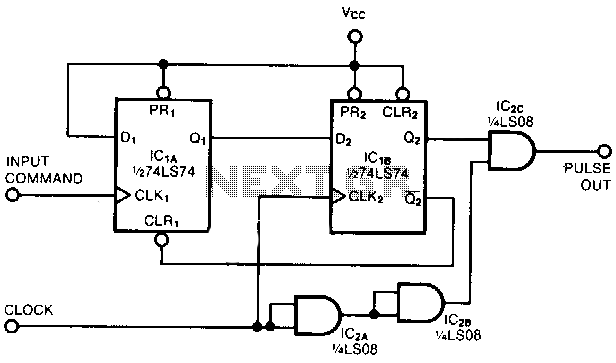
This circuit captures a single positive pulse from a square-wave train. After the rising edge of an input command, the pulse-out signal generates a replica of one positive pulse of the clock signal simultaneously with the next rising edge...
This broadband AM receiver allows monitoring of the shortwave radio band. The circuit is intentionally designed for low selectivity and exhibits maximum sensitivity in the frequency range of 6 to 20 MHz, which encompasses most shortwave broadcast stations. In...
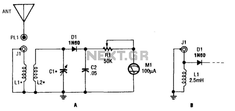
L1 and L2 form a tuned transformer with an optimum turns ratio of approximately 1:3. L2 and C1 are used to tune to the desired frequency. The frequency range can extend from 10 kHz to over 200 MHz, depending...
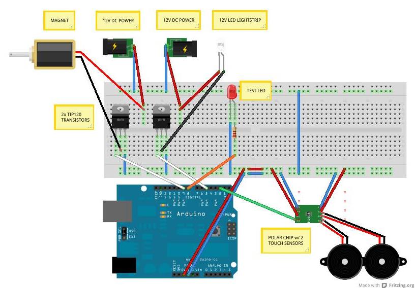
HeartWave visualizes pulse activity by converting heartbeats into wave patterns. One or two users can engage with HeartWave by placing their hands on sensors located on the sides of the tank. Each heartbeat activates a magnet momentarily, which pulls...

This circuit design generates a stable 1 kHz sine wave using an inverted Wien bridge configuration with components C1-R3 and C2-R4. It offers a variable output, low distortion, and low output impedance to ensure good overload capability. The circuit...
A simple triangle and square wave generator utilizing a common 1458 dual op-amp, capable of operating from very low frequencies up to approximately 10 kHz. The time interval for one half-cycle is determined by the product of resistance (R)...