
Triangle / Squarewave Generators
The triangle and square wave generator circuit employs a 1458 dual operational amplifier, which is known for its versatility in waveform generation. The circuit typically consists of a feedback network composed of resistors and capacitors that define the frequency response and waveform characteristics. In this configuration, one op-amp is used for generating the triangle wave, while the second op-amp can be configured to produce the square wave.
The frequency of operation is primarily influenced by the RC time constant, which is calculated as the product of the resistance (R) and capacitance (C) values within the feedback loop. This relationship allows for precise control over the frequency output by selecting appropriate resistor and capacitor values. For example, using a 47 kΩ resistor in conjunction with a capacitor can yield frequencies from a few hertz up to 10 kHz, depending on the specific values chosen.
The output current capability of approximately 10 milliamps makes this circuit suitable for driving small loads or interfacing with other electronic components. The amplitude of the triangle wave can be adjusted by varying the resistance in the feedback path, allowing for flexibility in the output signal level. Additionally, to address any DC offset present in the waveform, a capacitor can be placed in series with the output. This capacitor blocks DC components while allowing the AC waveform to pass, effectively centering the waveform around zero volts and enhancing the signal integrity.
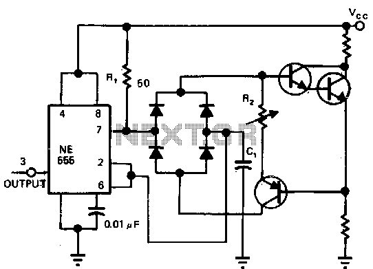
Overall, this triangle and square wave generator circuit offers a simple yet effective solution for generating low-frequency waveforms, making it a valuable tool for various applications in signal processing, testing, and modulation.A simple triangle/squarewave generator using a common 1458 dual op-amp that can be used from very low frequencies to about 10 Khz. The time interval for one half cycle is about R*C and the outputs will supply about 10 milliamps of current.
Triangle amplitude can be altered by adjusting the 47K resistor, and waveform offset can be removed b y adding a capacitor in series with the output. 🔗 External reference
Related Circuits
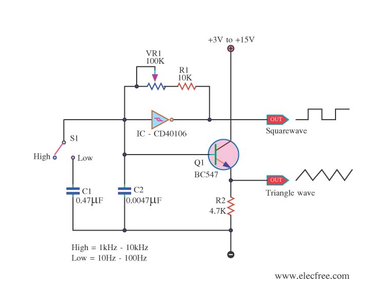
This is a circuit function generator that produces triangle and square wave signals. It utilizes an IC 40106 and a BC547 transistor. The variable resistor VR1 is used to control the frequency output, while switch S3 serves as a...
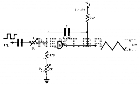
This fixed-frequency triangular waveform generator, driven by a TTL square wave, produces triangular waveforms with a peak-to-peak voltage of typically 16 V at frequencies reaching several MHz. The design utilizes a single AND open collector gate or an open...
The circuit illustrates a straightforward triangle and square wave generator utilizing a common dual operational amplifier, the LM1558, capable of producing very low frequencies around 10 kHz. The time interval for one half-cycle is approximately determined by the product...
This circuit is effective for testing audio circuits using broadband noise. It employs three inexpensive C-MOS integrated circuits (ICs) that produce a series of output pulses with randomly varying widths. The audio noise generator is designed to drive earphones...
Marx Generators are commonly utilized in pulsed power and high voltage applications to produce a high peak voltage pulse. The fundamental principle behind these generators involves charging several capacitors in parallel, followed by closing switches to connect them in...
Utilizing a single current source for both the charge and discharge paths in this circuit guarantees that the rise and fall times at the capacitor terminal are identical. A Darlington pair is employed to ensure consistent biasing of the...