
Tuned Rf Wavemeter
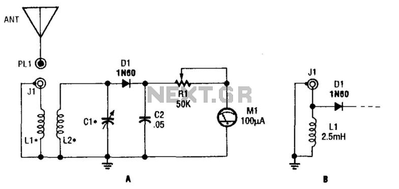
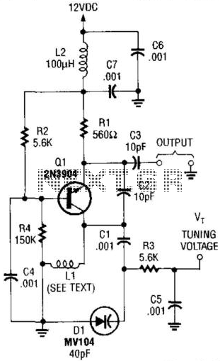
The circuit utilizes two inductors, L1 and L2, configured as a tuned transformer. The design aims for an optimal turns ratio of approximately 1:3, which facilitates effective energy transfer between the two inductors while allowing for impedance matching to the load. The tuning element, C1, is critical in determining the operational frequency of the circuit.
The frequency range supported by this configuration spans from 10 kHz to over 200 MHz. This wide range is achievable by adjusting the capacitance value of C1. For HF applications, a variable capacitor with a capacitance of 140 pF is appropriate, allowing fine-tuning of the circuit to achieve resonance at lower frequencies. In contrast, for VHF applications, a lower capacitance value of around 25 pF is recommended to accommodate the higher frequency range.
In addition to the tuned transformer configuration, the use of a 2.5 RF choke introduces an alternative functionality. This component can create an untuned wavemeter setup, which may be beneficial for specific applications where frequency measurement or monitoring is required without the need for precise tuning. The RF choke serves to block certain frequencies while allowing others to pass, thus providing a means to analyze the frequency response of the circuit.
Overall, this circuit design offers versatility in tuning and frequency management, making it suitable for a variety of RF applications. The careful selection of inductance and capacitance values is essential in achieving the desired performance characteristics. Ll and L2 form a tuned transformer. About a 1:3 turns ratio is optimum. L2 and CI tune to the desired frequency. The fre quency range can be 10 kHz to over 200 MHz, depending on the value of CI. For HF use, CI can be a 140-pF variable. For VHF, use about 25 pF. Use of a 2.5 RF choke will yield an untuned wavemeter. 🔗 External reference
Related Circuits

This design circuit is intended for sine wave oscillators, providing both sine and square wave outputs across a frequency range from below 20 Hz to above 20 KHz. The oscillation frequency can be easily adjusted by changing a single...
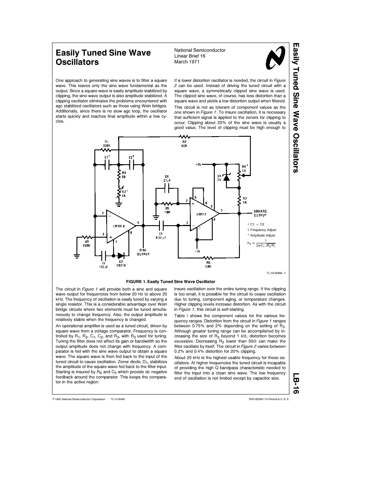
One approach to generating sine waves is to filter a square wave. This leaves only the sine wave fundamental as the output. If a lower distortion oscillator is needed, the circuit in Figure 2 can be used. Instead of...
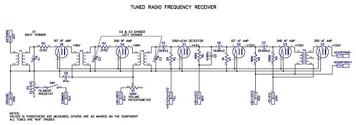
Tuned radio frequency receiver. A radio receiver consisting of several amplifier stages that... A tuned radio frequency (TRF) receiver is a type of radio receiver that utilizes multiple amplification stages to enhance the reception of radio frequency signals. The design...
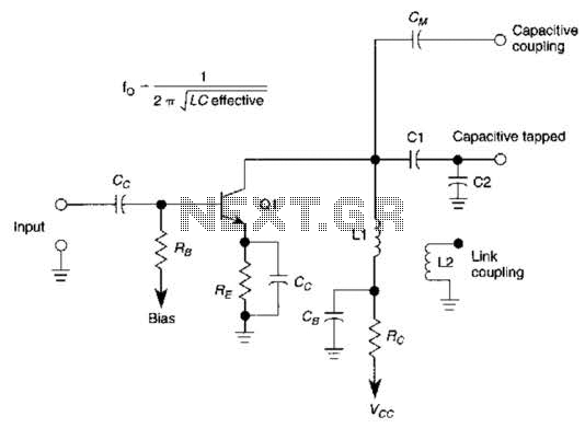
This basic tuned LC amplifier can be used with three output coupling methods: capacitive coupling output, capacitive tapped output, or link-coupled output. The tuned LC amplifier is a fundamental circuit used in various applications, including radio frequency (RF) amplification and...
This VHF VCO circuit operates within the frequency range of 30 to 200 MHz. Q1 may be substituted with a 2N3563 for frequencies exceeding 100 MHz. The inductor, L1, is selected to resonate at the desired frequency in conjunction...
This simple tuned radio frequency receiver was designed and constructed in the mid-1990s. The receiver was tested under urban and field conditions, in varying temperatures. This straightforward circuit exhibits high sensitivity, good sound quality, and reliability. A signal received...