
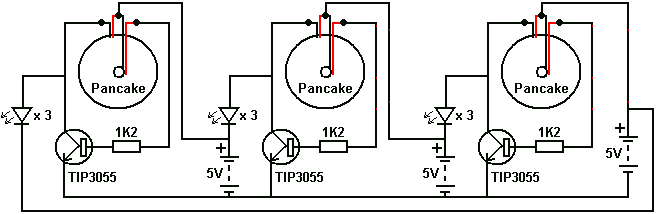
Advanced version of Joule Thief circuit
In electronic circuit design, particularly when dealing with light-sensitive applications, the accurate measurement of light intensity is crucial. A light meter serves as an essential tool in this context, providing precise quantification of light levels that can significantly influence circuit performance and component selection.
The light meter operates by converting light energy into an electrical signal, which can be displayed in various units such as lux or foot-candles. This measurement allows engineers to determine the optimal operating conditions for light-sensitive components, such as photodiodes, phototransistors, or light-dependent resistors (LDRs).
In designing circuits that rely on ambient light levels, such as automatic lighting systems or solar-powered devices, integrating a light meter can enhance reliability and efficiency. For instance, in a circuit where a phototransistor is used to control an LED based on light levels, the data obtained from the light meter can be used to calibrate the sensitivity of the phototransistor. This ensures that the LED only activates under specific light conditions, thereby conserving energy and prolonging the lifespan of the components involved.
Furthermore, the light meter can assist in troubleshooting and optimizing existing circuits. By providing real-time feedback on light levels, engineers can make informed adjustments to component values or configurations, ensuring that the circuit operates within its intended parameters.
In summary, the incorporation of a light meter into circuit design and analysis is a valuable practice that enhances the accuracy of light level assessments, ultimately leading to more effective and efficient electronic systems.When working with these circuits, I bought a light-meter to take the guesswork out of assessing light levels as the human eye is very bad at doing that. 🔗 External reference
Related Circuits
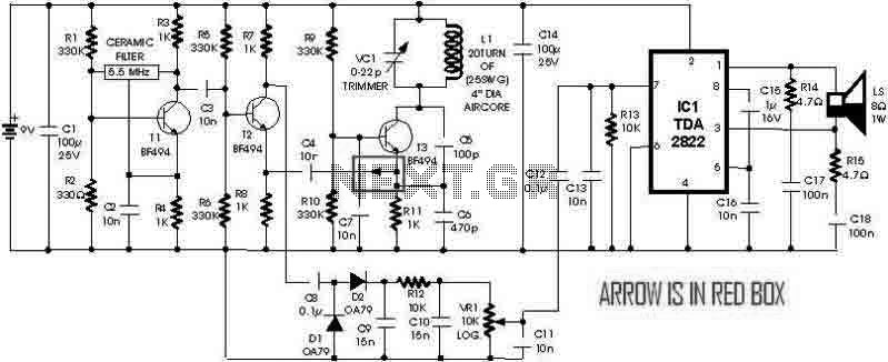
This is a simple metal detector utilizing a TDA2822 and several NPN transistors. An arrow indicates the signal flow direction from the Emitter of transistor T3 to the 10nF capacitor C4, which is opposite to the typical left-to-right flow...
This inductance meter serves as an adapter for a digital voltmeter (DVM), enabling the voltmeter to measure the value of inductors. The inductance meter is particularly useful in designing switch mode power supplies, as it often requires hand-winding coils...
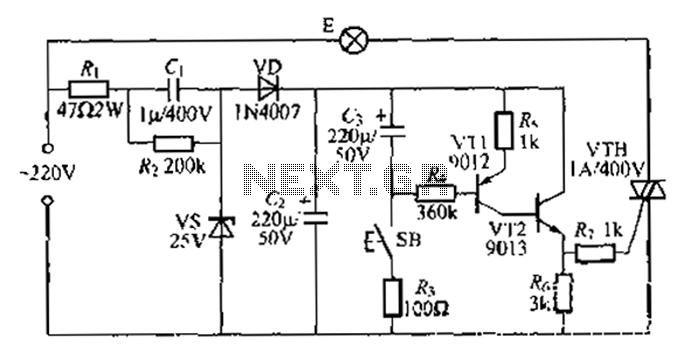
Another method employs a Zhu gall thyristor delay lamp circuit. Typically, a 220V AC supply is used, consisting of a step-down voltage half-wave rectifier circuit. The circuit outputs approximately 25V across the left and right terminals. At this point,...
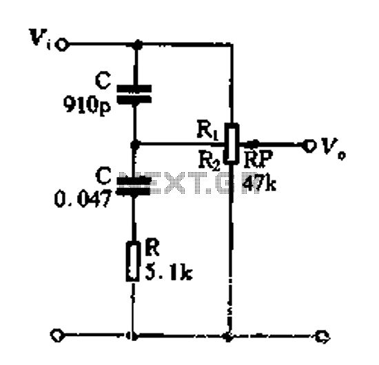
Figure 1-89 illustrates a loudness control circuit. A potentiometer is connected to ground, with 30% of the total resistance at the tap. When the slider arm is adjusted to the tap position, a midrange attenuation of 30 dB is...
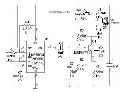
A cell phone jammer is an electronic device designed to obstruct the transmission of signals between a cell phone and its nearby base station. By transmitting on the same frequency as cell phones, the jammer generates significant interference, disrupting...
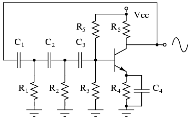
The phase shift oscillator produces a sine wave output in the audio frequency range. Resistive feedback from the collector results in negative feedback due to a 180-degree phase inversion from the base to the collector. The three 60-degree RC...