
Metal Detector circuit with TDA2822
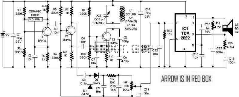
1) The coil L1 is a critical component, with the schematic suggesting 20 turns while the text mentions 15 turns. Either configuration may function, but the variable capacitor VC1 will differ. It is advisable to start with 15 turns.
2) VC1 has a range of 0-22pF. A minimum of 0pF is unnecessary and difficult to source. With a 15-turn coil, the optimal setting for VC1 is approximately 18pF, suggesting the use of a 5-15pF capacitor in parallel with a fixed capacitor of 5 or 10pF for easier sourcing and adjustment.
3) A 4-inch coil operating at 5.5MHz will result in a very limited detection range, which may be suitable for locating nails within walls behind plaster.
4) The V+ for the oscillator should be regulated and isolated from the audio amplifier to prevent interaction with the audio signal, as the audio amplifier can draw several hundred milliamps.
5) The resistance value for R2 is incorrectly specified as 330Ω; it should likely be 330kΩ to allow T1 to conduct.
6) Capacitors C11 and C13 are effectively in parallel, and the low-pass filter formed by VR1, C11, and C13 will have a varying cutoff frequency from infinity to 5kHz depending on the volume setting.
7) The power bypass capacitors C1 and C14 may not be effective at the 5.5MHz operating frequency. The detection oscillator is likely to lock onto the frequency of the ceramic filter, indicating that additional 0.1µF (100nF) capacitors are necessary to adequately filter the V+ for the oscillator.
The metal detector circuit is designed to operate at a frequency of 5.5MHz, which is typical for such devices. The use of a TDA2822 integrated circuit allows for efficient amplification of the audio signal generated by the detection process. The configuration of the NPN transistors plays a significant role in signal processing and amplification.
The coil L1, being the primary sensing element, must be constructed with precision to ensure optimal performance. The choice between 15 and 20 turns can affect the inductance and sensitivity of the detector. The variable capacitor VC1 serves to fine-tune the circuit's response, and its selection should be made with care to ensure it aligns with the operational requirements of the circuit.
In terms of power management, the circuit must ensure that the oscillator's power supply is stable and isolated to prevent noise from affecting the audio output. The incorrect resistance value for R2 could lead to malfunction, as it would prevent the transistor T1 from operating correctly, thereby affecting the entire detection process.
The filtering capacitors C11 and C13 are essential in shaping the frequency response of the audio output. The low-pass filter they form with VR1 allows for control over the audio signal's frequency range, which can be critical for distinguishing between different types of signals.
Lastly, the bypass capacitors C1 and C14 need to be carefully selected to match the operating frequency of the circuit. The addition of 0.1µF capacitors will help to smooth out any fluctuations in the power supply, ensuring that the oscillator operates reliably without interference from power supply noise. Overall, the design and component selection are crucial for the effective performance of the metal detector circuit.Here is a simple metal detector with TDA2822 and few NPN transistors. There is a small arrow connected from the Emitter of the T3 to the 10n Capacitor C4. That arrow is simply indicating signal flow as right to left in that particular wire, which is different from the remaining circuit's left to right. 1) The most critical component is the coil L1. The text says 15 turns and the schematic says 20 turns. I suppose either will work, but VC1 will be different. I would try 15 turns first. 2) VC1 is 0-22pF. A 0pF minimum is unnecessary, and it would be a difficult to find part. With a 15 turn coil, the nominal setting for VC1 is about 18pF, so a 5-15pF part in parallel with a 5 or 10pF fixed capacitor will be easier to find and easier to adjust. 3) The 4 inch coil and 5.5MHz operating frequency will give a very limited detection distance. Might be good for finding nails in the wall, behind the plaster. 4) The oscillator V+ should be regulated and isolated from the audio amplifier. Otherwise zero beat will interact with the audio, since the audio amplifier can draw a few hundred mA.
5) R2 value (330R) is wrong. It would prevent T1 from ever conducting. Maybe it's 330K. 6) C11 and C13 are basically in parallel. VR1/C11/C13 low pass frequency varies from infinity to 5kHz with the volume setting. 7) The power bypass capacitors C1 and C14 are unlikely to be effective at the 5.5MHz operating frequency. The detection oscillator will tend to lock on the ceramic filter's frequency. The circuit needs a few 0.1uF (100n) caps to filter the oscillator V+. 🔗 External reference
Related Circuits
Modify it to click and latch a relay when the button is pressed from anywhere in the house. Additionally, if possible, unlatch the relay when pressed again. A flip-flop circuit may be created to take the first signal and...
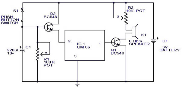
This circuit is a slight modification of a previous design. In the earlier version, the switch needed to be held down for the entire duration of the music playback. In this updated circuit, pressing the push button once charges...
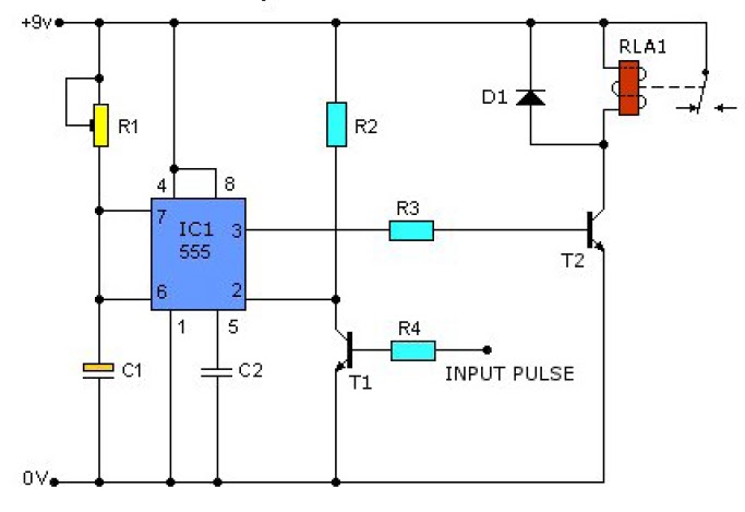
This causes T1 to conduct, pulling pin 2 of IC1 low. IC1 then enters a timing cycle, the duration of which is set by R1 and C1, resulting in pin 3 of IC1 going high. This action causes T2...

The circuit activates a light corresponding to the first button pressed in a "Who's First" game. Three stages are illustrated, but the circuit can be expanded to accommodate any number of buttons and lamps. The described circuit operates as a...
U1 is the 3817 integrated circuit, capable of directly driving the display. It can show time in either 12-hour or 24-hour format, schedule alarm sounds, and automatically turn on the radio at specified times. The display utilizes the FND500...
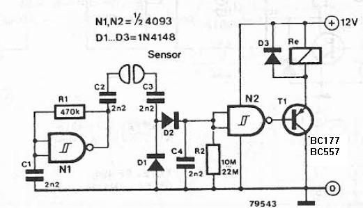
The liquid detector is a device designed to detect the presence of liquid using alternating voltage. This circuit can be constructed using common electronic components. The alternating voltage is generated by a gate with a Schmitt trigger function, acting...