
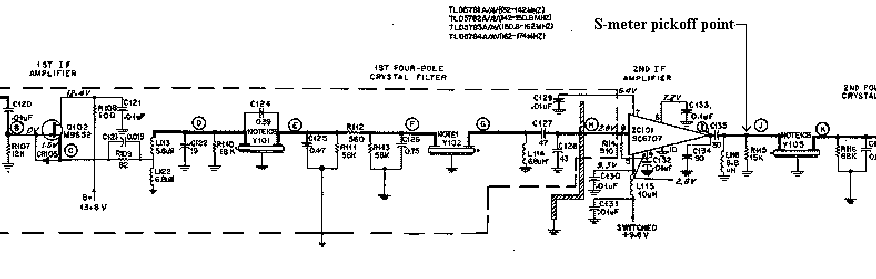
AGC / S-Meter

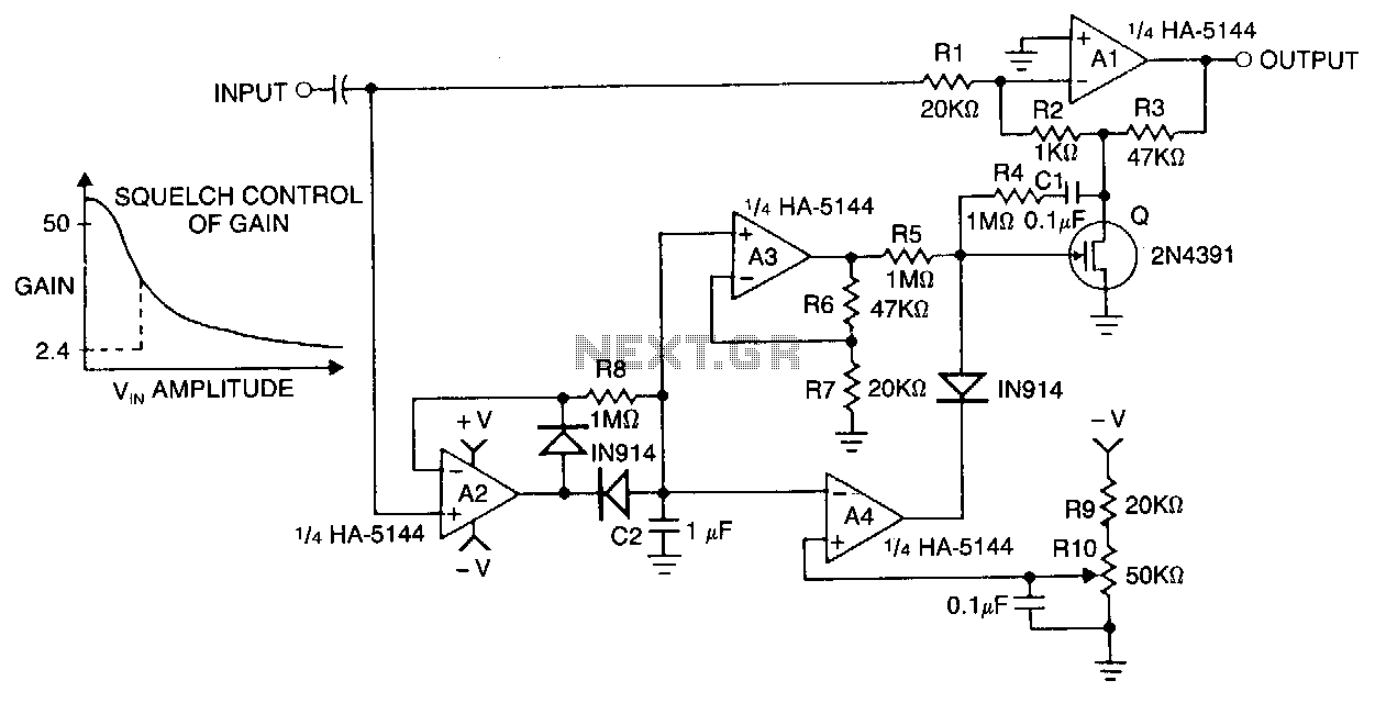
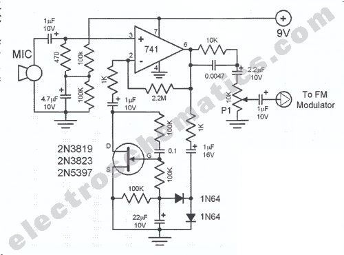
An Automatic Gain Control (AGC) circuit is essential for maintaining consistent output levels in audio applications, particularly in superheterodyne receivers. The AGC described consists of two distinct circuits, each tailored for specific operational requirements. The first circuit is versatile, accommodating audio amplifiers utilizing dual operational amplifiers such as the TL072, TL082, NE5532, and NE592 broadband amplifiers. This circuit is characterized by a response time of approximately 10 milliseconds and a hold-on time of about 2 seconds, making it suitable for general audio applications.
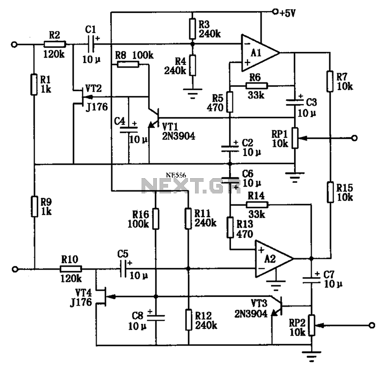
The second AGC circuit is more specialized, designed explicitly for audio frequency (AF) amplifiers with dual op-amps. This circuit mandates equal DC voltage levels at both inputs and outputs, along with a degree of insensitivity to fluctuations in supply voltage. These conditions are not met by the NE592-based audio amplifier, limiting its applicability. The second circuit excels in mitigating volume fluctuations due to its higher gain, achieved through a bipolar transistor instead of a field-effect transistor (FET). This configuration allows for more effective signal management, particularly in scenarios with high signal levels.
The output voltage at the AF stage, even under strong signal conditions, is limited to a maximum of 2 Vss, which aids in maintaining signal integrity. Notably, the design eliminates the need for a coupling capacitor, as the DC levels across the op-amp inputs and outputs remain consistent. To enhance functionality, a sensitive 50 to 100 µA meter can be integrated in series with the discharging resistor (R1), providing a visual indication of the relative signal strength, often referred to as an "S-meter." For optimal performance, R1 should be adjusted from its original value of 220 kOhm to around 100 kOhm, which will slightly reduce the hold-on time.
When a positive AF signal swing exceeding 1 V occurs, the 100 µF capacitor charges up to approximately 5.2 V, which subsequently allows current to flow through the base of the transistor, leading to a reduction in volume during strong signal reception. Calibration of the S-meter presents a challenge compared to the first AGC circuit due to limited voltage variation at the capacitor. A zero-point adjustment can be performed using a 10 kOhm trim potentiometer. The resistance of Rv, which influences the pointer swing of the S-meter, typically requires empirical determination, with a suggested value around 4.7 kOhm. This AGC design effectively stabilizes audio output levels while providing a mechanism for signal strength indication, thereby enhancing the overall performance of audio amplification systems.You can build an automatic gain control AGC for the superhet receiver with only a few additional components. The first AGC circuit is more universal. It is suitable for audio amplifiers with dual op amps like TL072, TL082, NE5532 and the broadband amp NE592 too.
The second circuit is only suitable for AF amplifiers with dual op amps because it requires equal DC voltage levels at inputs and outputs as well as insensitivity of them against supply voltage changes. This two conditions aren't available for an audio amplifier based on the NE592. Both AGC circuits have a response time of about 10 ms and a hold-on time of 2 s. I didn't show the op amp circuitry in favour of a simple presentation of the AGC schematic. The second AGC circuit can eliminate volume changes much better compared to the first circuit. The reason of this is the higher controller gain (bipolar transistor instead of a FET). Even in case of very strong receive signal, the measured AF stage output voltage against ground, is only 2 Vss at its maximum. No coupling capacitor is needed because all DC levels at the dual op amp inputs and outputs have the same rate.
Whoever likes, can set a sensitive 50 ... 100 uA meter in series with the discharging resistor R1 for indicating the relative signal strength "S-meter". R1 should be reduced from originally 220 kohms down to around 100 kOhm, whereby the hold-on time gets a little bit shorter then.
With a positive AF signal swing of >1 Vs the 100 uF capacitor will get charged up to 5.2 V. The transistor conducts by means of the now flowing base current. This causes here also a volume reduction at strong receive signals. Calibrating the S meter isn't so easy like the first circuit. There is less voltage change available at the capacitor. Zero point adjustment with the 10 kohm trim potentiometer must be done first. Rv is responsible for the pointer swing. The Rv resistance has to be defined by something trying, it is about 4,7 kohm. 🔗 External reference
Related Circuits
The artwork style of the operational amplifier and the meter face suggests that it is an ACC design from an old issue of ACC Notes. The second image was scanned, and the text below was written from scratch. If...
Automatic gain control (AGC) is a valuable feature found in various audio amplifier circuits, including tape recorders, telephone speakerphones, communication systems, and public address (PA) systems. This circuit utilizes a HA-5144 quad operational amplifier (op-amp) and a field-effect transistor...
The Audio Automatic Gain Control (AGC) circuit monitors the output signal level of an audio preamplifier. When the input signal increases, the AGC circuit automatically reduces the amplifier's gain. Conversely, when the input signal decreases, the AGC circuit increases...
The LC72146 is a Phase-Locked Loop (PLL) Frequency Synthesizer LSI circuit designed for electronic tuning in car stereo systems. This component facilitates the development of high-performance, multifunctional electronic tuning systems across VHF, MW, and LW bands. It is manufactured...
Automatic Gain Control (AGC) is a circuit design that maintains a consistent level of amplification for sound or radio frequency signals. If the signal is too low, the AGC increases the gain to ensure the output remains at a...
Commonly referred to as an automatic gain control (AGC) circuit, it is primarily utilized in receivers. This circuit maintains a constant output voltage amplitude despite variations in the input signal amplitude. It ensures that the receiver can effectively process...