
Motorola Micor S-meter Driver
This circuit serves as a signal strength indicator for radio receivers, providing a straightforward method to visualize signal levels through an analog S-meter. The design's core functionality revolves around sampling the intermediate frequency (IF) signal, rectifying it to produce a DC voltage, and amplifying this voltage to drive an analog meter or a repeater controller input.
The operational amplifier (LM324) plays a critical role in ensuring that the output voltage remains stable and is not affected by the load connected to it, which is essential for maintaining accurate signal strength readings. The inclusion of a calibration potentiometer allows for user adjustments, enabling the circuit to be tailored to different receiver sensitivities and user preferences.
In terms of construction, the circuit's compact size allows for easy integration into existing setups. The use of breadboard wiring facilitates prototyping, while the option to mount the circuit within the receiver chassis ensures a clean and organized installation. The choice of components, such as germanium diodes for rectification and appropriate capacitors for filtering and isolation, significantly impacts the circuit's performance, particularly in maintaining high sensitivity and accuracy.
Overall, while the circuit presents a basic approach to signal strength measurement, careful attention to component selection and circuit layout is necessary to optimize performance and mitigate potential issues related to loading effects on the IF strip. As the design evolves, further refinements may enhance its practicality and reliability in real-world applications.The artwork style of the opamp and of the meter face both suggest that is is an ACC design and is from an old issue of ACC Notes. I have credited it as such. I scanned the second image and wrote the text below from scratch. If anybody can locate the original ACC Notes text I will add it, and a reference to the original issue.
Provide an analog s-meter output proportional to signal input. This DC voltage can be fed to a analog input of a repeater controller. The controller can be programmed to give an indication of signal strength, perhaps by varying the frequency of the courtesy beep. Just remember that intermod, desense, and other extraneous RF noise will false the reading. Looking at the two schematics below you will see that the circuit point after the first IF amplifier and before the second IF filter is identified as "Point H" on the UHF schematic and as "Point J" on the VHF schematic.
This is the point of interest. The circuit below provides a dc voltage from near zero to just over 5 volts dc depending on signal input to allow a local meter or the ACC controllers s-meter input to be driven. A gain (calibration) pot is provided to allow the user to set the full-scale s-meter calibration as desired.
The 68pf capacitor provides DC isolation from the IF amplifier output, the two diodes and the 100pf capacitor produce the varying DC level, and the LM324 opamp acts as an variable gain buffer amplifier and prevents whatever load there is (an analog meter or the repeater controller analog input) from dragging down the DC level. Your target is a 0 to +5vDC voltage. The 68pf capacitor may need to have it`s value adjusted for a 10m or 6m receiver. A low band Micor uses 5. 26 MHz for an IF frequency (or 5. 36 if needed to dodge a birdie), whereas high band, UHF, 800MHz and 900MHz receivers use 11. 7 (or 11. 8) Mhz. Update, July 2009: This circuit needs more development to be really practical: Several people have reported trying several variations of this circuit and all have the problem that it loads down the IF strip (and therefore makes the receiver less sensitive).
I would surmise that a high impedance RF amp needs to be inserted between the pick-off capacitor and the CR1/CR2 rectifier. Construction can be simple breadboard wiring as the whole circuit will fit on a Radio Shack 1 7/8" by 2 7/8" breadboard.
The IC should be mounted in a socket to allow easy replacement. You can power the circuit from a tap on the +9. 6vDC buss in the receiver, or use a 7808, 78M08 or 78L08 voltage regulator fed from +12vDC. The circuit should not load the receiver in any way and should not degrade the receivers performance. Try to keep the lead from "Point H" (UHF) or "Point J" (VHF) reasonably short. You may need to add some series resistance between the 68pf cap and the receiver IF tap point. The two detector diodes (CR1 and CR2 should be germanium for best performance (germanium has a lower voltage drop than silicon) and can be any signal diode.
The board could be mounted inside the reciever chassis, and you could use one of the unused frequency select lines to bring the op-amp DC voltage output to the meter or to the controller analog input. The circuit is pretty basic, just sample the IF signal strength pre-limiter with a small-value capacitor, rectify it, and amplify/buffer it with a DC-coupled op-amp circuit.
Because of the way the ACC does the S-meter, you`ll never really get a real signal strength reading. It`s calibrated from "S zero" to "S nine plus sixty". Assuming 6 dB per S-unit, that means there is better than 104 dB of dynamic range available, which in reality, would never be realized in an FM repeater. The other problem is that the ACC meter is scaled linearly, while real S-meters are logarithmic, so again, it`s not all that accurate except for re
🔗 External reference
Related Circuits
This is a very simple, low-cost, Hi-Fi quality power amplifier. It can be built in five different configurations, as shown in the table, ranging from 20 W to 80 W RMS. The Hi-Fi quality power amplifier circuit is designed to...
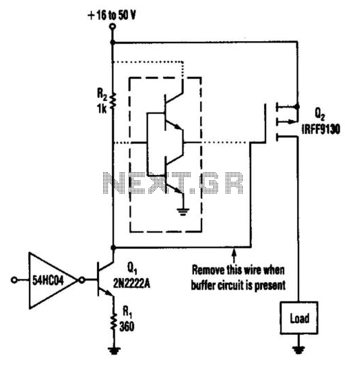
This circuit operates from a 16- to 50-V supply. Adding the buffer circuit (within the dashed lines) offers 100-ns switching times. Otherwise, the circuit switches in 1 µs. Q1 and R1 form a switched current source of about 12...
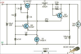
This circuit is designed to drive 1W LEDs that are commonly available. It addresses their non-linear voltage-to-current relationship and variations in forward voltage. The circuit utilizes a constant current driver configuration to ensure that the LEDs operate efficiently while maintaining...
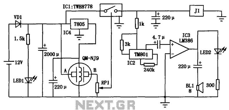
The alcohol detection alarm controller circuit is illustrated in the figure. It utilizes the QM-NJ9 alcohol gas sensor, which detects the presence of alcohol vapors. When alcohol is detected, the resistance between the AB-QM-NJ9 decreases, causing the wiper of...
This article aims to utilize an old PC as a simple controller. Many outdated PCs, such as the 8088, 8086, 80286, 80386, or even 80486, have become obsolete systems. This design employs an 8-bit LPT printer parallel data port...
This chapter was removed from Applied Robotics 2 due to space constraints. It addresses general motor control issues and details the construction of a 5-amp motor driver. The principles discussed can be applied to larger motor controllers. Although commercially...