
Pll receiver
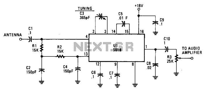
The described AM circuit is based on the 561B, which is a low-frequency amplifier designed to operate in the amplitude modulation (AM) band. The absence of an inductance/capacitance tuning circuit simplifies the design, relying solely on the 365 pF capacitor for frequency selection. This capacitor effectively tunes the circuit to the desired frequency by creating a resonant circuit when combined with the input impedance of the 561B.
The circuit requires an external antenna to capture AM signals effectively. The performance of the circuit can be significantly improved by using a high-quality antenna, which can increase the received signal strength and improve the overall audio quality. A solid ground connection is also critical, as it minimizes noise and interference, ensuring a clearer reception of AM signals.
For users looking to enhance the circuit's performance further, integrating a broadband amplifier before the receiver is advisable. This amplifier will boost weak signals, allowing for better reception of distant AM stations. When implementing an amplifier, it is crucial to monitor the input voltage levels to avoid distortion and potential damage to the components. The specified limit of 0.5 volts RMS serves as a safeguard to maintain the integrity of the circuit's operation.
In summary, this AM circuit with a 561B and a 365 pF capacitor provides a straightforward yet effective solution for receiving AM signals, particularly when paired with a quality antenna and proper grounding. The option to add a broadband amplifier can further enhance its capabilities, making it a versatile choice for AM radio applications.This simple AM circuit uses a 561B. There's no inductance/capacitance tuning circuit. The 365 pF capacitor connected between pins 2 and 3 does all the tuning. The circuit needs a good outside antenna and a solid ground. And if you want to further improve operation, stick a broadband amplifier in front of the receiver. Just make sure the input voltage does not climb over 0.5 volt rms. 🔗 External reference
Related Circuits
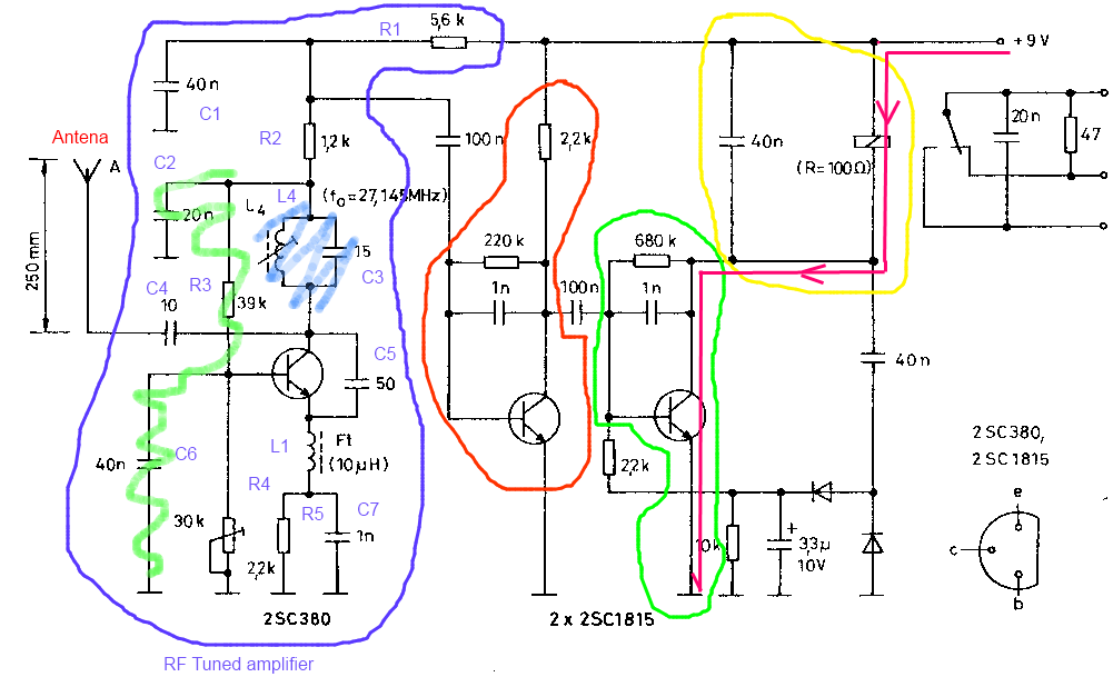
The circuit described is a toy car receiver, which operates similarly to the transmitter but in reverse and with additional filtering. The receiver is tuned to a frequency of 27.145 MHz to capture signals at this frequency. Following the...
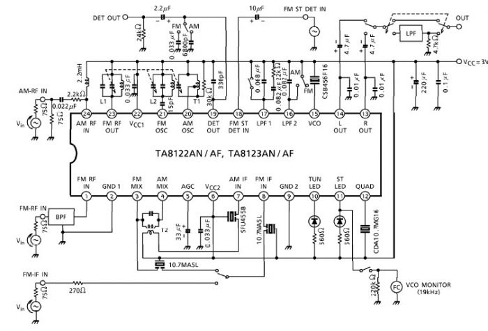
A simple low-power AM/FM radio receiver electronic project can be designed using the TA8122 integrated AM/FM receiver, manufactured by Toshiba Semiconductor. This radio receiver circuit is suitable for portable radio applications and similar devices. The TA8122 radio receiver circuit...

The main oscillator is printed in blue and is voltage controlled. In this construction, the VCO range is 88 to 108 MHz. As you can see from the blue arrows, some energy goes to an amplifier and some energy...
This schematic illustrates a high-quality AM radio receiver circuit centered around the MK484 AM radio integrated circuit (IC). The MK484 is known for its high sensitivity and superior performance, featuring only three leads and housed in a TO-92 package....
The ADM1066 is a configurable supervisory and sequencing device that provides a single-chip solution for supply monitoring and sequencing in systems with multiple power supplies. In addition to these capabilities, the ADM1066 features a 12-bit ADC and six 8-bit...
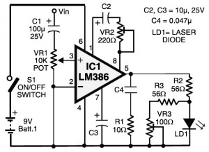
Laser communication system circuit diagram. The circuit module consists of a transmitter and a receiver that utilize the IC LM386. It is powered by a 9V battery. The laser communication system is designed to facilitate wireless data transmission using modulated...