
Air Ioniser circuit
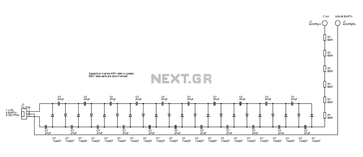
The Cockcroft-Walton ladder circuit is a type of voltage multiplier that utilizes capacitors and diodes to achieve high output voltages from a lower input AC voltage. In this design, capacitors are arranged in a series configuration where each capacitor is charged to a peak voltage of approximately 340V from the mains supply. The diodes are oriented in such a way that they allow current to flow in only one direction, effectively rectifying the AC voltage and allowing the capacitors to charge up to their peak voltage. The sum of the voltages across the capacitors results in a high voltage output, which can reach up to around 7kV at the top of the ladder.
The output of the ladder is connected to a high-value resistor, which serves to limit the current available at the output. This is crucial for safety, as high voltages can be dangerous. The resistor must be rated for high voltage operation, or alternatively, multiple lower-rated resistors can be connected in series to achieve the desired resistance value without exceeding their voltage ratings.
The design is specifically tailored for use with 220V to 240V mains power. For applications utilizing 110V mains supply, a longer ladder configuration would be necessary to achieve equivalent voltage multiplication.
The ion emission phenomenon is a notable characteristic of this high voltage generator. When a sharp point, such as a dressmaking pin, is connected to the high voltage output, it creates a localized electric field that ionizes the surrounding air. This ionization leads to the generation of negatively charged ions, which can be felt as a gentle breeze. The audible hiss and faint glow observed at the sharp point are indicative of ongoing ionization.
To demonstrate the effectiveness of the ion generator, a simple apparatus can be constructed using a copper wire and a folded aluminum foil strip. The aluminum foil acts as a lightweight rotor, which can be set in motion by the ion breeze produced at the sharp points. This setup not only serves as an engaging demonstration of the principles of ionization but also illustrates the potential for further experimentation and modification to enhance performance or explore new applications. The use of a grounded aluminum foil sheet beneath the device can also help increase the ionization effect by providing a larger area for charge accumulation and improving the overall efficiency of the ion emission process.A basic mains driven Cockroft ladder high voltage generator is shown in the schematic. This is functionally the same as a project in Electronics Today International many years ago. The peak mains voltage of 340V appears across each capacitor and this is negative with respect to mains neutral and the surrounding environment. The orientation of the diodes defines the polarity. As the capacitors are in series, the voltages sum and at the top of the ladder about 7kV is present. A high value resistor is used at the output end to current limit the output. It is important to use a high voltage rated resistor or a string of lower voltage ones in series, so that the resistors maintain their stated resistance value.
This design is for 220 to 240V mains power and a double length ladder would be needed for 110V supply. If a single dressmaking pin or other sharp point is connected to the EHT output you will be able to feel a slight breeze of negatively charged air molecules coming from the end of the point. The high charge density at the sharp point causes this ionisation and the negative ions are then repelled from the negatively charged pin, causing this ion breeze.
You can also hear the point emitting a slight hiss and in very dark conditions you can just see the point glow slightly. The ionisation at the point tends to physically degrade it over time and this reduces the ionisation occurng there.
Some commercially available air ionisers have precision shaped points of special alloys to counter this. One fun way to make sure that your ioniser is still ionising is to use the ion breeze thrust from the needles to spin a rotating emitter pair.
A12cm long piece of stout copper wire is soldered into a 4mm plug and this is plugged into the EHT output. The top end of the wire has an ordinary steel dressmaking pin soldered to it. This is the point on which the spinning emitter arrangement balances. A section of aluminium foil about 20 cm long and 6cm wide is folded multiple times down its length until it is about 20cm long and 0.5cm wide.
This gives the foil more strength. Try not to leave any sharp edges or points as these may ionise the air in unwanted places on the structure. If you can find a thick aluminium foil pie-tin then this is better. You could just cut that to the desired width and there will be no need for the multiple folding. The head end of two pins are folded into each end of the foil strip pointing in opposite directions. Then the strip is folded in the middle so that it forms an inverted V shape. This can then be placed on top of the balance point. When the power is turned on the ion breeze will push the inverted V round and it will remain spinning as long as there is sufficient ionisation happening at the points.
The spin speed can be increased by putting a sheet of aluminium foil connected by wire to the ground terminal underneath the whole arrangement. I put a white sheet of paper over this to collect the fine dust and smoke particles that the ionised air precipitates from the atmosphere.
I'm sure that this design can be changed and improved in myriad ways, but this experiment demonstrates that spinning your ioniser emitters under their own ion thrust is very easy. Maybe the spinning action encourages ion emission by moving the needles through relatively un-ionised air.
Maybe you could aerofoil shape the structure to gently fan air up or down past the system. There are many possibilities, and the spinning emitter has great novelty value. 🔗 External reference
Related Circuits
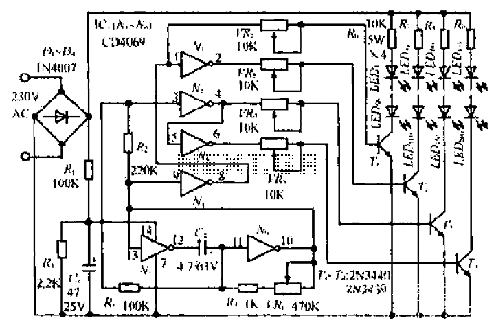
An air bridge after the bullock Phi Beach in Sichuan utilizes direct beam lights. Control is implemented for six buildings with filtered output at specific voltage levels. The system includes a small 4H servant for pressure control, and components...
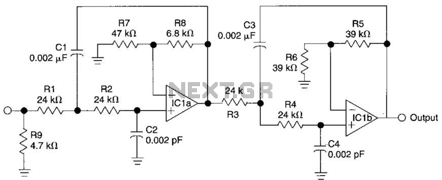
This circuit is a fourth-order low-pass filter designed for operation at kilohertz frequencies. The component values for resistors R1, R2, and capacitors C1, C2, as well as resistors R3, R4 and capacitors C3, C4 can be adjusted for functionality...
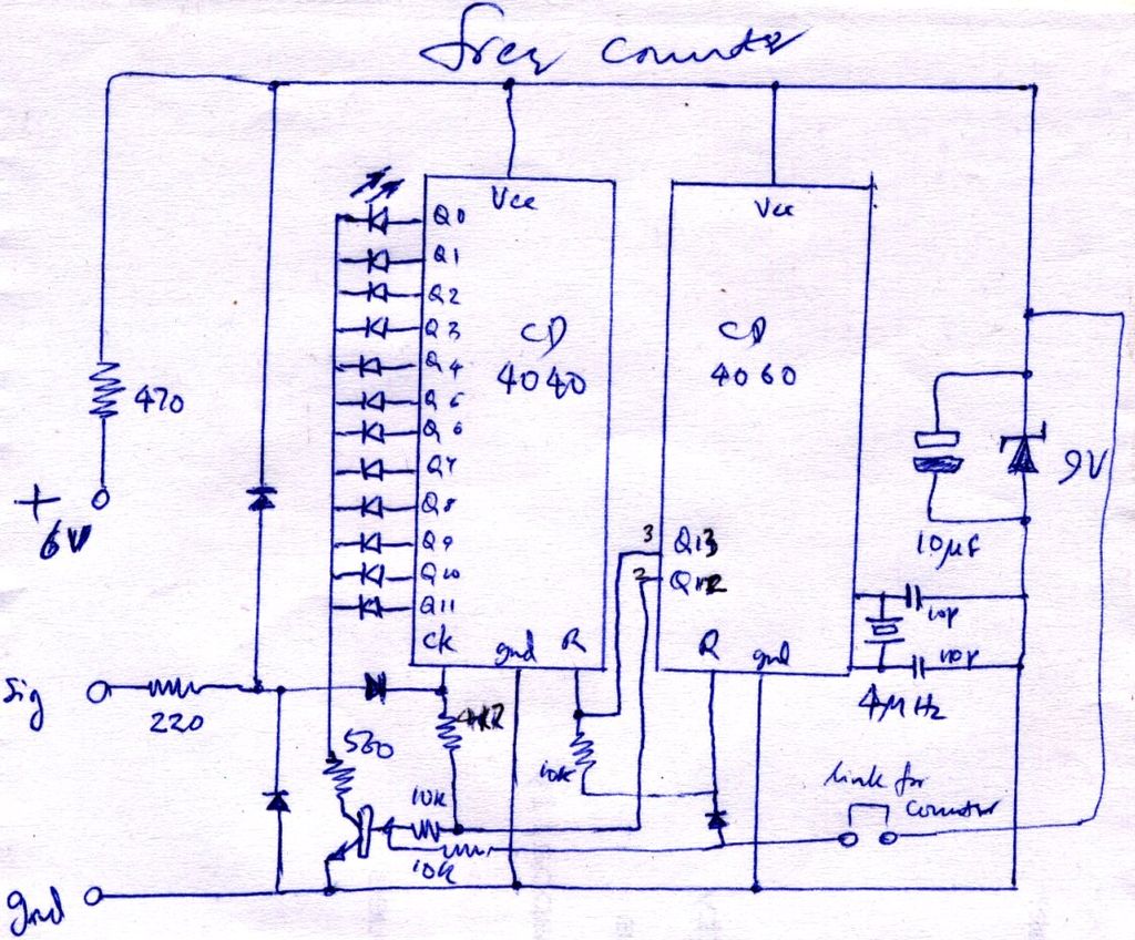
The construction is nearly complete, and a circuit diagram has been created. The design has been finalized and documented on paper. The circuit diagram represents a critical stage in the development of an electronic project, serving as a blueprint for...
The enhancement circuit, as depicted, increases the high-frequency components of the video signal, thereby improving the contrast of the television image. It can be connected between the VCR and the TV SCART input. The circuit utilizes transistor T1 for...

The digital circuit that is particularly useful is the One-Shot circuit, also known as a monostable multivibrator circuit. This circuit exhibits a specific behavior where it generates a single output pulse in response to an input trigger. The One-Shot circuit,...
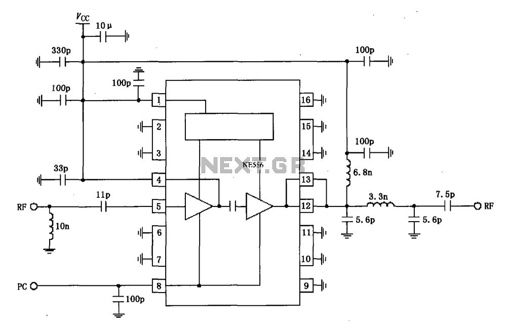
The RF2104 830MHz amplifier circuit operates as illustrated in the figure. A radio frequency (RF) signal enters through a 5-foot input, passes through a preamplifier, and is then amplified by an amplifier stage at the 12-pin output. The circuit...