
Alarm Circuits

The high power siren circuit operates using a complementary push-pull configuration, which enhances efficiency and sound output. The BC557 transistor serves as the PNP component of the pair, while the BC337 functions as the NPN transistor. This arrangement allows for effective switching and amplification of the audio signal generated during oscillation.
Capacitor C2 plays a crucial role in the timing and frequency modulation of the circuit. Its charging and discharging characteristics directly influence the oscillation frequency. Resistor R8 is selected to control the discharge rate of C2, thereby affecting how quickly the circuit transitions from a low frequency to a high frequency and vice versa.
The circuit's functionality can be further refined by adjusting the values of the resistors and capacitors involved. This allows for customization of the siren's sound characteristics to suit specific requirements. Additionally, the use of a potentiometer in place of R8 can provide variable control over the discharge rate, enabling the user to fine-tune the frequency response dynamically.
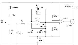
Overall, this high power siren circuit is versatile and can be adapted for various applications, including alarms, warning signals, or other audio signaling needs. Properly designed, it can deliver a powerful and effective sound output suitable for demanding environments.High Power Siren Circuit This article is all about a comparatively strong siren circuit useful for any purpose. A complementary transistor pair (BC 557 & 337) is arranged as an oscillator, directly drives the speaker.
Transistor Q1(BC 557) is used to provide full charging of capacitor C2. When P1 is pressed, C2 discharges through R8 and the circuit starts oscillating at a low frequency that increases slowly until a high frequency steady tone is reached and it is kept. When P2 is released C2 starts discharging and and output frequency slowly decreases. When C2 is charged fully the circuit stops oscillations. Tips. Adjust the 🔗 External reference
Related Circuits
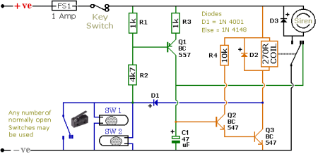
The schematic illustrates a Simple Motorcycle Alarm Circuit Diagram created by Ron J. It incorporates micro-switches to safeguard removable panels and... The Simple Motorcycle Alarm Circuit Diagram is designed to enhance the security of motorcycles by utilizing a series of...
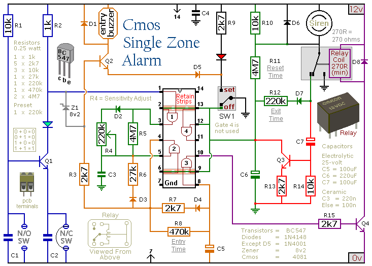
This circuit includes automatic exit and entry delays, a timed bell cut-off, and a system reset feature. It is designed to support both normally-open and normally-closed switches and can accommodate standard input devices such as pressure mats, magnetic reed...
A rain sensor alarm circuit is a useful device for alerting when rainfall occurs. The rain detector circuit presented is straightforward, utilizing only three components while maintaining high sensitivity to detect rain or moisture. The sensor can be constructed...
When the switch is pressed, capacitor C3 charges through resistor R4 with a time constant of 0.47 seconds. Upon releasing the switch, C3 discharges more slowly through resistors R7 and R3, with a time constant of approximately 5 seconds....
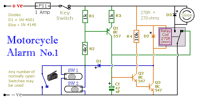
This circuit includes a timed output and an automatic reset feature. It can be manually operated using a key switch or a concealed switch. By incorporating an external relay, the circuit will automatically engage or immobilize the machine each...
This circuit emits a beep and/or illuminates an LED when someone touches the door handle from outside. The alarm will sound until the circuit is switched off. The described circuit functions as a touch-sensitive alarm system designed to enhance security...
Warning: include(partials/cookie-banner.php): Failed to open stream: Permission denied in /var/www/html/nextgr/view-circuit.php on line 713
Warning: include(): Failed opening 'partials/cookie-banner.php' for inclusion (include_path='.:/usr/share/php') in /var/www/html/nextgr/view-circuit.php on line 713