
Alarm Digital Clock-DS1307
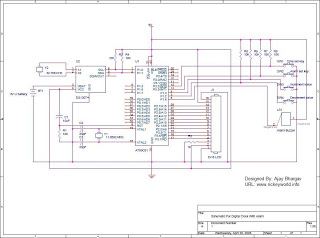
The DS1307 real-time clock module is designed for precise timekeeping applications, utilizing the I2C communication protocol for seamless integration with microcontrollers such as the AT89C51. The connection of the 2x16 HD44780 LCD to port 2 allows for clear display of time and status indicators. The microcontroller's P1.0 and P1.1 pins serve critical roles in the I2C communication, where P1.0 acts as the serial clock line (SCL) and P1.1 as the serial data line (SDA). This configuration enables efficient data transfer between the microcontroller and the DS1307, allowing for real-time updates of the displayed time.
Upon initialization, the DS1307 provides a default date and time, which can be modified through the microcontroller's programming. The inclusion of a backup battery ensures that the clock maintains its settings and continues to keep time accurately, even during power outages. The acknowledgment process within the I2C protocol is essential for verifying data transmission, where the receiver signals successful data reception by manipulating the SDA line.
The assembly source code provided for this application is tailored for the Keil environment, allowing for straightforward programming of the AT89C51 microcontroller. The availability of the Clock.asm and Clock.hex files facilitates easy deployment of the digital clock functionality. For those interested in customizing the code, disassembling software is recommended, enabling users to modify the existing hex file to suit their specific needs. Additionally, the schematic diagram in PDF format serves as a valuable resource for understanding the circuit layout and connections, providing a comprehensive guide for anyone looking to replicate or enhance the digital clock project.DS1307 is a hardware realtime clock, which works on I2C protocol. Better graphics using the same old fashioned alphanumeric LCD (type HD44780). Icons which shows the status for Alarm ON/OFF state, which gives a nice and cute look to the clock. Circuit diagram for the digital clock. 2x16 LCD is connected to the port 2 of AT89C51. P1. 0 of uC will pr ovide the SCL (serial clock) and P1. 1 SDA (serial data) for I2C communication. When the power supply is switched on it will give you the default date and time, but later you can change it to the desired value. After setting once, the backup battery will keep the clock ticking even after the power is not there.
Acknowledgement-After sending of one byte of data the reciever has to acknowledge the sender for the successful reception. for this the sender make the SDA line high and reciever pulls down the SDA low, which tells the sender that data has reached safely.
Now the source code written in assembly, basically implements the I2C protocol. the assembly source written for Keil. Download for Clock. asm and the Clock. hex file for programming the controller. Digital Clock Schematic is available in PDF format can be downloaded. For ppl who wants to edit the code but they dont have the A51 Macro assembler/Keil, they can use the following software to disassemble the hex file and change it according to their need. The disassembling software can be downloaded from following link: 🔗 External reference
Related Circuits

This design circuit is for a digital voltmeter. The integrated circuit ICL7107 serves as a 3-1/2 digit LED analog-to-digital converter (A/D converter). It includes an internal voltage reference, high isolation analog switches, sequential control logic, and display drivers. An...
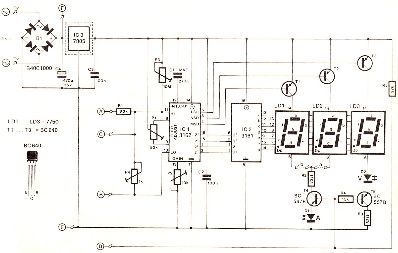
This voltage/current (V/I) display module is well-suited for integration into an existing DC power supply, providing precise readings of the set voltage or the current consumption of the load. The voltage measurement range features a decimal point indicator (LD3),...
The reason why I am using an LCD display is because it allows me to display many characters and it doesn't need to be refreshed as 7-segment LED displays. Also, the interface requires less I/O pins. For this project,...

This is an infrared-based broken beam alarm designed to protect doors and entry passages. It emits a loud alarm when someone crosses the invisible infrared barrier. The infrared-based broken beam alarm system operates by utilizing a pair of infrared emitters...
Unlike other alarm circuits that provide only normally-open or normally-closed configurations, this alarm circuit works for both configurations. The circuit is designed to enhance flexibility in alarm systems. This dual-configuration alarm circuit utilizes a versatile relay that can be set...

In some cases, a differential input is needed for voltage measurement. By using a single operational amplifier, it is possible to construct an adapter that provides a floating voltage reference. To achieve a differential input for voltage measurement using an...