
Burglar Alarm Works for Both N.O and N.C Contacts
This dual-configuration alarm circuit utilizes a versatile relay that can be set to operate in either normally-open (NO) or normally-closed (NC) mode. The core component of this circuit is a relay, which acts as a switch that can control the flow of current based on the input from a sensor or trigger. In the NO configuration, the circuit remains open until the alarm condition is activated, allowing current to flow when the alarm is triggered. Conversely, in the NC configuration, the circuit remains closed under normal conditions, interrupting the current flow when the alarm is activated.
The circuit typically includes a power supply, a triggering device (such as a motion sensor, door switch, or smoke detector), and the relay itself. A diode may be included across the relay coil to prevent back EMF from damaging other components when the relay is de-energized. Additionally, a resistor may be used to limit the current flowing through the triggering device and ensure its proper operation.
The flexibility of this alarm circuit makes it suitable for various applications, including home security systems, industrial monitoring, and safety alarms. By accommodating both configurations, users can easily integrate this circuit into existing systems or customize it to meet specific requirements, enhancing overall functionality and reliability.Unlike other alarm circuit that provide normally-open only or normally-closed only configuration, this alarm circuit work for both configurations. The.. 🔗 External reference
Related Circuits
This simple circuit is sure to have the police beating a path to your door - however, it has the added advantage of alerting you to their presence even before their footsteps fall on the doormat. The circuit transmits...
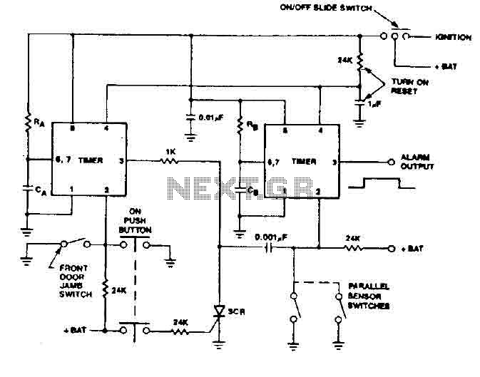
The 555 timer generates a reliable delay, enabling the driver to deactivate the alarm and eliminating the need for an external control switch that could be compromised. Additionally, the RCS prevents the activation of timer B unless it is...
This schematic diagram illustrates a water level sensor, detector, and monitor circuit. An alarm is also integrated into this circuit. It is designed to detect any fluid with a resistance below 900K ohms. The water level sensor circuit typically employs conductive...
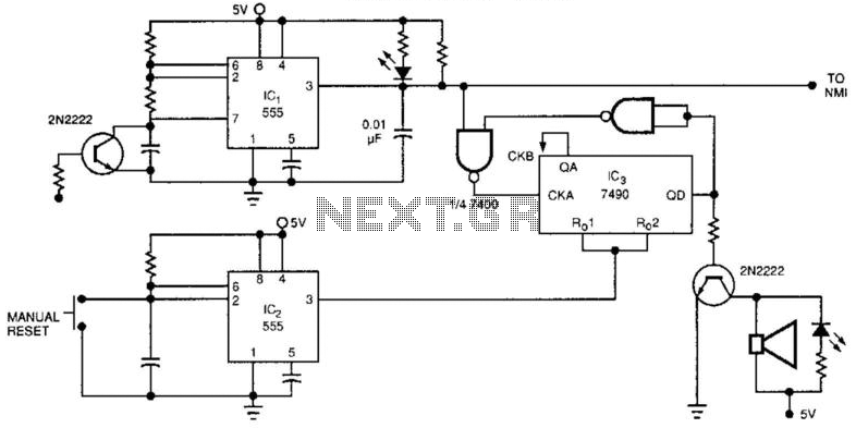
The watchdog timer includes a counter, IC3, alongside the standard retriggerable 555 timer, IC1. The counter will sound an audible alarm if the watchdog timer attempts to reset a specified number of times (8, in the case of the...
The following circuit illustrates a Sun Up Alarm Light Alarm Circuit Diagram. This circuit is based on the 555 Integrated Circuit (IC). Features include simplicity and cost-effectiveness. The Sun Up Alarm Light Alarm Circuit employs the 555 timer IC in...

A low-cost, high-performance programmable home security system utilizing a few LDRs as input sensors. When the sensors are triggered, the system can dial a user-specified phone number using a built-in DTMF generator and activate a high-power audio alarm and...
Warning: include(partials/cookie-banner.php): Failed to open stream: Permission denied in /var/www/html/nextgr/view-circuit.php on line 713
Warning: include(): Failed opening 'partials/cookie-banner.php' for inclusion (include_path='.:/usr/share/php') in /var/www/html/nextgr/view-circuit.php on line 713