
ALKALINE CHARGER
The circuit for recharging alkaline cells utilizes a unique configuration of transistors that allows for an oscillating charge transfer mechanism. This design features a charging unit that consists of a capacitor, which stores energy, and a transistor that is configured to operate in a feedback loop. The oscillation generated by the transistor is essential for the effective transfer of energy from the capacitor to the cell being charged.
The blinking orange LED serves as an indicator of the charging status. Under normal conditions, when charging a cell with a nominal voltage of 1.37V, the LED will blink approximately five times per second. In the case of a deeply discharged cell, the LED will blink at a higher frequency, indicating that the circuit is actively charging the cell. As the cell approaches full charge, the blinking rate will gradually decrease until it ceases, signaling that the cell is fully charged.
The circuit is designed to allow for trickle charging, which maintains the cell voltage at around 1.6V. This feature is crucial for preventing overcharging and ensuring the longevity of the alkaline cell. To calibrate the circuit for optimal performance, it is necessary to connect a fresh, unused alkaline cell and adjust the trimmer potentiometer. This adjustment should be made until the oscillations are observed, followed by a slight reduction in the adjustment until the oscillations cease. This process ensures that the circuit is properly tuned for the specific characteristics of the alkaline cell being charged.
Only the specified transistors should be employed in the circuit to ensure reliability and efficiency. The choice of components is critical, as they must be capable of handling the oscillation frequency and the charging current without overheating or failing. Proper attention to the circuit layout and component selection will enhance the overall performance and safety of the alkaline cell charging system.This circuit was specifically designed to recharge alkaline cells. The unusual connection of the transistor in each charging unit will cause it to oscillate, on and off, thus transferring the charge accumulated in the capacitor to the cell. The orange LED will blink for around 5 times a second for a 1.37V cell. For a totally discharged cell the blinking is faster but it will decrease until it will come to a stop when the cell is charged.
You may leave the cell in the charger as it will trickle charge and keep it at around 1.6V. To set the correct voltage you have to connect a fresh, unused cell and adjust the trimmer until oscillations set in, then go back a little until no oscillation is present and the circuit is ready to operate. You should use only the specified transistors, 🔗 External reference
Related Circuits
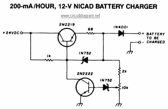
A 12V NiCAD battery charger circuit with a charging rate of 200mA per hour. This circuit initially charges the battery at 75mA until it reaches a full charge, after which the current is reduced to a trickle rate. The...

This is a simple yet effective charger for lead-acid batteries. It utilizes a 12-volt car bulb as both a current regulator and a charge status indicator. The described circuit is an innovative approach to charging lead-acid batteries. It employs...
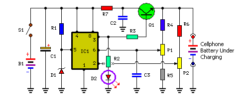
Stops charging when the battery is fully charged. Portable unit for charging mobile phones. Cellphone battery management is a significant issue while traveling, as power supply can be limited. The described circuit functions as an intelligent battery charger designed to...
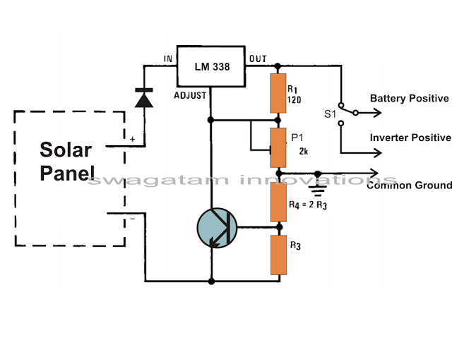
Solar panels are well-known devices that convert solar energy or sunlight into electricity. A solar panel consists of discrete sections of individual photovoltaic cells, each capable of generating a small amount of electrical power, typically between 1.5 to 3...
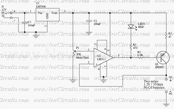
The circuit presented in the above schematic has been designed to charge automatically two series 350mAh "AAA" size batteries. Set the 20KOhms multiturn potentiometer to get a 2.78V on the 3rd pin of the LM311 which is a comparator....
The car battery charging current is automatically limited to 4.2A. If there is a 600mV voltage on R1 (indicating 4A flowing through it), the T1 transistor begins to conduct. This prevents excessive charging current as the base current of...
Warning: include(partials/cookie-banner.php): Failed to open stream: Permission denied in /var/www/html/nextgr/view-circuit.php on line 713
Warning: include(): Failed opening 'partials/cookie-banner.php' for inclusion (include_path='.:/usr/share/php') in /var/www/html/nextgr/view-circuit.php on line 713